Mouse killer

A technology for eradicating rodents and rats, applied in animal traps, applications, animal husbandry, etc., to achieve reliable action, good effect of eradicating rodents, and simple structure

Inactive Publication Date: 2015-09-09
方鹏羽
View PDF4 Cites 3 Cited by
  • Summary
  • Abstract
  • Description
  • Claims
  • Application Information

AI Technical Summary

Problems solved by technology

[0005] Therefore, present existing rodent co

Method used


Image

  • Mouse killer
  • Mouse killer
  • Mouse killer

Examples


Embodiment Construction

[0030] The present invention will be further described below in conjunction with accompanying drawing:

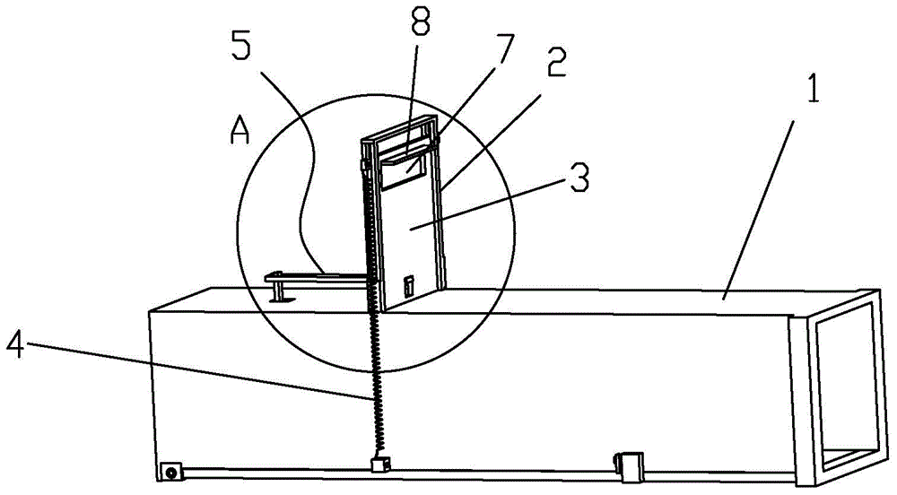
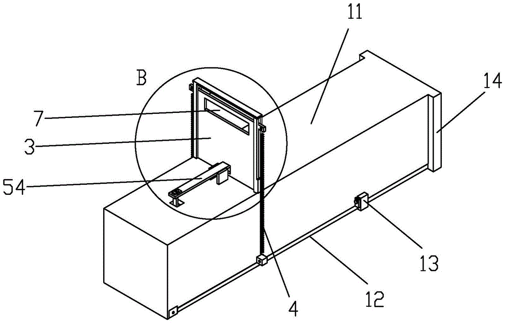
[0031] Such as Figure 1 to Figure 6 As shown, a rodent extermination device includes a box body 1 that can be drilled into by mice 200. The middle part of the box body 1 is provided with a bracket 2, and the bracket 2 is provided with a gate 3 that can be raised and lowered along it. Between the two sides of the gate 3 and the box body 1, springs 4 that enable the gate 3 to move downward to kill mice in the box body 1 are respectively provided. The trigger mechanism 5 that makes the gate 3 move downward under the action of the spring 4 .

[0032] Such as Figure 2 to Figure 6 As shown, the trigger mechanism 5 includes a trigger plate 51 located on the front side of the gate 3 and hinged in the box body 1. The trigger plate 51 is provided with a locking portion 52 exposed to the box body 1. The trigger mechanism 5 also includes a locking position 53 arranged on the gate ...


PUM


Abstract

The invention discloses a mouse killer which comprises a box allowing a mouse to plunge. A support is arranged in the middle of the box, a gate capable of ascending and descending along the support is arranged on the support, springs capable of enabling the gate to move downward to kill the mouse in the box are arranged between the two sides of the gate and the box, and a trigger mechanism capable of being triggered by the mouse to enable the gate to move downwards under the action of the springs is arranged on the box. The mouse killer is simple in structure and good in mouse killing effect.

Description

【Technical field】 [0001] The invention relates to a rodent exterminator. 【Background technique】 [0002] Existing deratization equipment is generally exposed, or only catching must be manually killed, and along with the evolution of rodents, the effect of deratization is getting worse and worse. [0003] There are many types of rodent control equipment, and the more common ones are mouse traps, mouse glue, and high-voltage power grids. There is a kind of folk instrument, the wooden box for smashing rats. The rats are lured into the wooden box or basket, the mechanism is triggered, and the wooden board above the wooden box or basket is dropped with heavy objects to crush the rats to death. The device uses heavy objects to press the body of the rats. The heavy objects must be heavy enough. The whole device is bulky, and it is an entry type or a semi-open type of deratization, which will cause the rats to be alert. [0004] Mouse traps and mouse glue are widely used products ...

Claims


Application Information

Patent Timeline
IPC IPC(8): A01M23/20
Inventor 方鹏羽
Owner 方鹏羽
Why Eureka
Try Eureka