
Metal plate conveying and flattening mechanism for electronic accessories

A technology for accessories and sheet metal, applied in the field of sheet metal conveying and flattening mechanism for electronic accessories, can solve the problems of easy crushing of hands, small size of sheet metal parts, hidden safety hazards, etc., and achieves good flattening effect and high degree of automation , Feeding accurate effect

Active Publication Date: 2015-09-09
江苏盐城龙湖文化产业发展有限公司
View PDF6 Cites 13 Cited by
  • Summary
  • Abstract
  • Description
  • Claims
  • Application Information

AI Technical Summary

Problems solved by technology

[0002] In some electronic products or electronic equipment, many sheet metal parts need to be flattened after the stamping is completed due to flatness requirements. Because the volume of the sheet metal parts used in electronic equipment is small, and the existing sheet metal parts The material is generally loaded manually. Due to the small size of the sheet metal parts, it is relatively troublesome to place the material manually. When the hand is not retracted in time after discharging, it is easy to collide with the pressed block. , the hands are easily crushed, causing work-related injuries and potential safety hazards

Method used


Image

  • Metal plate conveying and flattening mechanism for electronic accessories
  • Metal plate conveying and flattening mechanism for electronic accessories
  • Metal plate conveying and flattening mechanism for electronic accessories

Examples


Embodiment

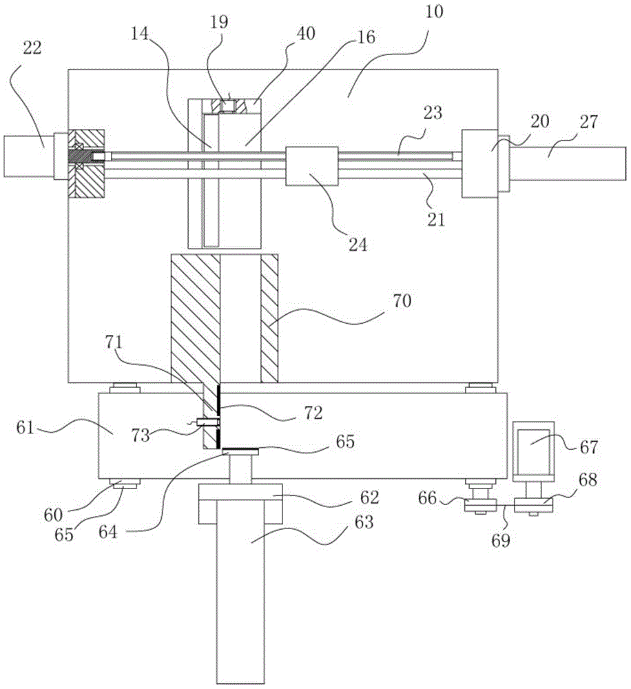
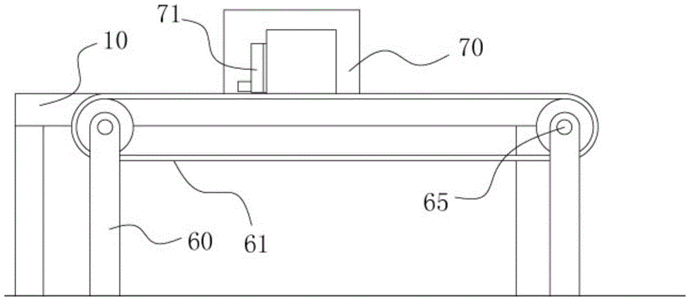
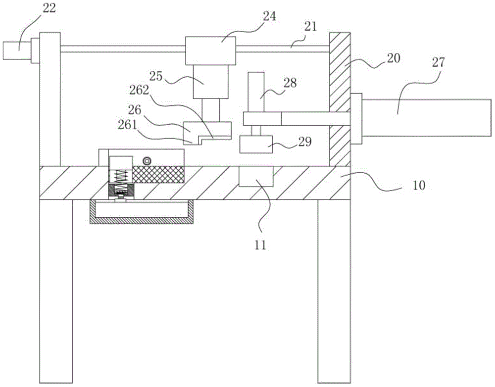
[0018] Example: see Figures 1 to 4 As shown, a sheet metal conveying and flattening mechanism for electronic accessories includes a frame 10 and a conveying frame 60. Binder groove 11, binder groove 11 is on the right side of groove 15, and the left and right ends of the top plate of frame 10 is fixed with support plate 20, and the two ends of stop bar 21 are fixed on two support plates 20, and drive motor 22 is fixed on one of the supporting plates 20, and the output shaft of the drive motor 22 extends into the socket provided in the supporting plate 20 and is hinged in the socket through a bearing. One end of the adjusting screw 23 has a spline portion, and the spline portion Stretch in this socket and insert in the spline hole that the output shaft of drive motor 22 has, the other end of adjustment screw rod 23 is hinged on another support plate 20, and moving block 24 is screwed in adjustment screw rod 23 and Insert sleeve in the limit rod 21, the bottom of the moving bl...


PUM


Abstract

The invention discloses a metal plate conveying and flattening mechanism for electronic accessories. The metal plate conveying and flattening mechanism comprises a framework and a conveying frame, the conveying frame is arranged on the front side wall of the framework, a groove and a pressing groove are formed in a top plate of the framework, the pressing groove is formed in the right side of the groove, supporting plates are fixed at the left end and the right end of the top plate of the framework, two ends of a limit rod are fixed onto the two supporting plates, a driving motor is fixed onto one supporting plate, an output shaft of the driving motor extends into an inserting hole in the supporting plate and hinged into the inserting hole through a bearing, a spline is arranged at one end of an adjusting screw, extends into the inserting hole and is inserted into a spine hole in the output shaft of the driving motor, the other end of the adjusting screw is hinged onto the other supporting plate, a movable block is screwed in the adjusting screw and inserted into the limit rod, and a pushing cylinder is fixed at the bottom of the movable block. The electronic accessories can be automatically conveyed and fed by a metal plate, a compression block is controlled to press down the electronic accessories, and the metal plate conveying and flattening mechanism is precise in feeding, fine in flattening effect and high in automation degree.

Description

Technical field: [0001] The invention relates to the technical field of electronic component equipment processing, and more specifically relates to a sheet metal conveying and flattening mechanism for electronic components. Background technique: [0002] In some electronic products or electronic equipment, many sheet metal parts need to be flattened after the stamping is completed due to flatness requirements. Because the volume of the sheet metal parts used in electronic equipment is small, and the existing sheet metal parts The material is generally loaded manually. Due to the small size of the sheet metal parts, it is relatively troublesome to place the material manually. When the hand is not retracted in time after discharging, it is easy to collide with the pressed block. , the hands are easily crushed, causing work-related injuries, and having potential safety hazards. Invention content: [0003] The purpose of the present invention is to address the deficiencies in...

Claims


Application Information

Patent Timeline
Patent Type & Authority Applications(China)
IPC IPC(8): B21D43/00
CPCB21D43/003B21D43/02
Inventor 华锋
Owner 江苏盐城龙湖文化产业发展有限公司
Learn More