Electronic sliding table

A sliding table, electronic technology, applied in the direction of large fixed members, metal processing machinery parts, metal processing equipment, etc., can solve the problems of high noise, complicated design, etc., to achieve low frictional energy consumption, ingenious and simple design, low frictional resistance Effect

Inactive Publication Date: 2015-09-09
宁波麦科斯机器人科技有限公司
View PDF9 Cites 7 Cited by
  • Summary
  • Abstract
  • Description
  • Claims
  • Application Information

AI Technical Summary

Problems solved by technology

[0003] In order to solve the above-mentioned technical problems of complicated design and high noise, the present invention provides an electronic slide table with simple design and low running noise

Method used


Image

  • Electronic sliding table
  • Electronic sliding table
  • Electronic sliding table

Examples


Embodiment 1

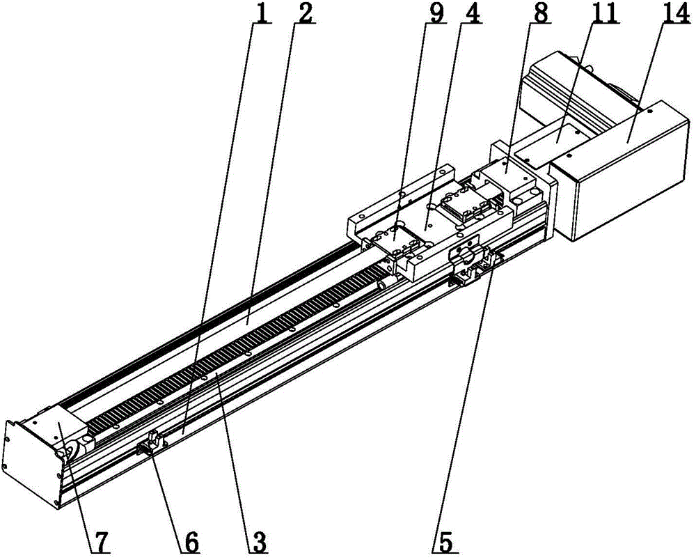
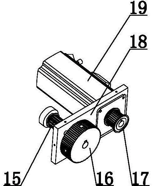
[0018] like figure 1 , 2 , The electronic sliding table shown in 3 and 4 includes a sliding table base 1, a guide rail 3 is provided on the sliding table base 1, a slidable sliding fixed block structure is provided on the guide rail 3, and the two ends of the sliding table base 1 A front fixed block 7 and a rear fixed block 8 are respectively provided, and the rear fixed block 8 is connected with the tail end fixed block 11, and the tail end fixed block 11 is provided with a driving structure for driving the movable sliding fixed block structure, and the described sliding fixed block structure includes a sliding The fixed block 4, the driving structure includes a servo motor a19, the tail end fixed block 11 is connected with the motor fixed block 18, the motor fixed block 18 is provided with a servo motor a19, the servo motor a19 servo motor shaft is provided with a synchronous wheel a17, and the synchronous wheel a17 is the same There is a synchronous wheel b16 on the side, ...

Embodiment 2

[0021] like Figure 5 , 6 , 7, the difference between this embodiment and embodiment 1 is that the sliding and fixing block structure includes a sliding and fixing block 4, the driving structure includes a service motor a19, the tail end fixing block 11 is connected with the motor fixing block 18, and the motor fixing block 18 There is a servo motor a19 on the top, and the servo motor shaft of the servo motor a19 is provided with a synchronous wheel a17, and the same side of the synchronous wheel a17 is provided with a synchronous wheel b16, and a rotating belt is arranged between the synchronous wheel a17 and the synchronous wheel b16, and the synchronous wheel b16 passes through the motor Fixed block 18 is connected with synchronous wheel c15, and described synchronous wheel c15 is positioned at tail end fixed block 11, and cover block 13 is housed on back fixed block 8 and tail end fixed block 11, and casing 14 is housed on motor fixed block 18, front fixed The block 7 is ...

Embodiment 3

[0023] like Figure 8 , 9 , 10, the difference between this embodiment and Embodiment 1 is that the sliding and fixing block structure includes a sliding and fixing block 4, and the driving structure includes a servo motor b26, and the motor head of the servo motor b26 is connected to the screw rod 21 through a coupling 23, and the screw Rod 21 is located between front fixed block 7 and rear fixed block 8, and front fixed block 7 inwall is provided with buffer head 25, and sliding fixed block 4 is connected with screw mandrel 21 by guide rail slide block 29, and screw mandrel 21 is provided with screw mandrel. Nut 22.

[0024] During use, the sliding and fixing block 4 is driven to move back and forth by the screw mandrel 21 .


PUM


Abstract

The invention relates to a mechanical transmission device and particularly relates to an electronic sliding table. The electronic sliding table comprises a sliding table base, a guide rail is arranged on the sliding table base, a sliding fixation block structure, a front fixation block and a rear fixation block are arranged at the two ends of the sliding table base respectively, the rear fixation block is connected with a tail end fixation block, and a driving structure for driving the sliding fixation block structure to move is arranged in the tail end fixation block. The electronic sliding table has the advantages of being ingenious and simple in design, low in noise, wide in use range, convenient to mount, high in accuracy and acceptable to the majority of users.

Description

technical field [0001] The invention relates to a mechanical transmission device, especially an electronic slide table. Background technique [0002] Linear transmission devices are widely used, but there are still many problems in many equipments at present, such as complicated design, inconvenient movement, high failure rate and loud noise. Contents of the invention [0003] In order to solve the above-mentioned technical problems of complicated design and high noise, the present invention provides an electronic slide table with simple design and low running noise. [0004] Technical scheme of the present invention is as follows: [0005] The electronic slide table includes a slide table base, a guide rail is provided on the slide table base, a slidable sliding fixed block structure is provided on the guide rail, a front fixed block and a rear fixed block are respectively provided at both ends of the slide table base, and a rear fixed block is arranged on the rear The ...

Claims


Application Information

Patent Timeline
Patent Type & Authority Applications(China)
IPC IPC(8): B23Q1/01B23Q1/58B23Q5/36B23Q5/40
CPCB23Q1/017B23Q1/58B23Q5/36B23Q5/40
Inventor 冯翔宇
Owner 宁波麦科斯机器人科技有限公司
Why Eureka
Try Eureka