Improved vertical lathe centering clamp

A technology of centering fixtures and vertical lathes, which is applied in the direction of clamping, positioning devices, clamping devices, etc., can solve the problems of large loss of spare parts, difficulty in machine tool crashes, short maintenance cycles, etc., and achieve simple centering structure and stable fixture accuracy , easy recovery effect

Inactive Publication Date: 2015-09-09
CITIC DICASTAL
View PDF6 Cites 0 Cited by
  • Summary
  • Abstract
  • Description
  • Claims
  • Application Information

AI Technical Summary

Problems solved by technology

This kind of fixture has disadvantages such as short maintenance period, large loss of spare parts, long time to confirm the accuracy of fixture parts replacement, long time for fixture maintenance, short maintenance cycle, and difficult recovery of abnormal machine tool crashes. , balance out-of-tolerance products, jump out-of-tolerance products, etc., seriously delaying the machining yield

Method used


Image

  • Improved vertical lathe centering clamp

Examples


Embodiment Construction

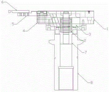
[0008] Improved centering fixture for vertical lathe, including power chuck main body 1, center disc spring 2, compression head 3, telescopic claw 4, small chuck pulling claw 5, small chuck pulling plate 6, telescopic head 7, machine tool pull rod head 8. The main body of the power chuck 1 is fixed to the base of the machine tool fixture by bolts, the telescopic head 7 is connected with the pull rod of the machine tool cylinder, the telescopic claw 4 is connected with the small chuck pulling claw 5, and the small chuck pulling claw 5 is connected with the small chuck pulling plate 6, The small chuck pulling plate 6 is connected with the radial slide seat of the fixture, the compression head 3 is connected with the telescopic head 7, and the center disc spring 2 is installed in the telescopic head. When clamping is loosened, the pull rod of the oil cylinder moves upwards and downwards, pushing the compression head 3 and the telescopic head 7 to move up and down, and drives the ...


PUM


Abstract

The invention discloses an improved vertical lathe centering clamp comprising a powered chuck body (1), a central disk spring (2), a compressing head (3), a telescopic claw (4), a small chuck pulling claw (5), a small chuck pulling plate (6), a telescopic head (7), and a machine tool pull rod head (8); the powered chuck body (1) is fixed on a machine tool clamp base through bolts; the telescopic head (7) is connected with a machine tool hydraulic cylinder pull rod; the telescopic claw (4) is connected with the small chuck pulling claw (5); the small chuck pulling claw (5) is connected with the small chuck pulling plate (6); the small chuck pulling plate (6) is connected with a clamp radial sliding seat; the compressing head (3) is connected with the telescopic head (7); and the central disk spring (2) is installed inside the telescopic head. Being simple in center locating structure, and with most connectors of the original clamp being saved, the purpose of stabilizing the accuracy of the clamp can be achieved by the improved vertical lathe centering clamp; and the simplification of the spare parts of the clamp allows the maintenance of the clamp to be done with fewer people and allows the clamp to be easily restored.

Description

technical field [0001] The invention relates to a positioning device, which is mainly used for positioning a wheel processing jig. Background technique [0002] At present, the vertical lathe automatic wheel processing jig commonly used in China is composed of a floating plate, a vertical lathe slide, a spring, and a linear bearing. The floating plate in the main body of the fixture moves up and down, pulling the sliding seat on the positioning plate of the fixture to realize radial sliding positioning. This kind of fixture has disadvantages such as short maintenance period, large loss of spare parts, long time to confirm the accuracy of fixture parts replacement, long time for fixture maintenance, short maintenance cycle, and difficult recovery of abnormal machine tool crashes. , Balance out-of-tolerance products, jump out-of-tolerance products, etc., seriously delaying the machining yield. Contents of the invention [0003] In order to solve the above problems, the pre...

Claims


Application Information

Patent Timeline
Patent Type & Authority Applications(China)
IPC IPC(8): B23Q3/00
CPCB23Q3/00B23Q2703/04B23Q2703/10
Inventor 孙栋梁郭建东刘伟东李玉东陈学武张金东
Owner CITIC DICASTAL
Why Eureka
Try Eureka