Method and device for obtaining cross-section by rotary cutting of bar material

A rotary, cross-section technology, applied in metal processing and other directions, can solve problems such as cross-section burrs, flash, filter rod cross-section deformation, etc., and achieve the effect of accurate reflection information, clear cross-section imaging, and strong practical value.

Active Publication Date: 2017-01-18
SHANGHAI PUSHUO AUTOMATION
View PDF6 Cites 0 Cited by
  • Summary
  • Abstract
  • Description
  • Claims
  • Application Information

AI Technical Summary

Problems solved by technology

Especially in the detection of grooved filter rod cross-section in the tobacco industry, because the filter rod is relatively soft, it is easy to deform during the cutting process, and it is difficult to cut a good-quality cross-section to be tested in actual production
[0003] At present, the existing cutting method of fixing the filter rod and rotating the cutter has the following disadvantages: First, during the cutting process of the cutter entering the knife, the blade is easy to squeeze the filter rod to a certain extent, and the cross section of the filter rod will be deformed due to extrusion. Deformation occurs; secondly, during the cutting process, the section will produce burrs and flashes
The above problems will lead to inaccurate analysis of the cross-sectional information of the filter rod, making it difficult to meet the high-precision detection requirements

Method used


Image

  • Method and device for obtaining cross-section by rotary cutting of bar material
  • Method and device for obtaining cross-section by rotary cutting of bar material
  • Method and device for obtaining cross-section by rotary cutting of bar material

Examples


Embodiment Construction

[0035] The present invention will be described in detail below in conjunction with the accompanying drawings.

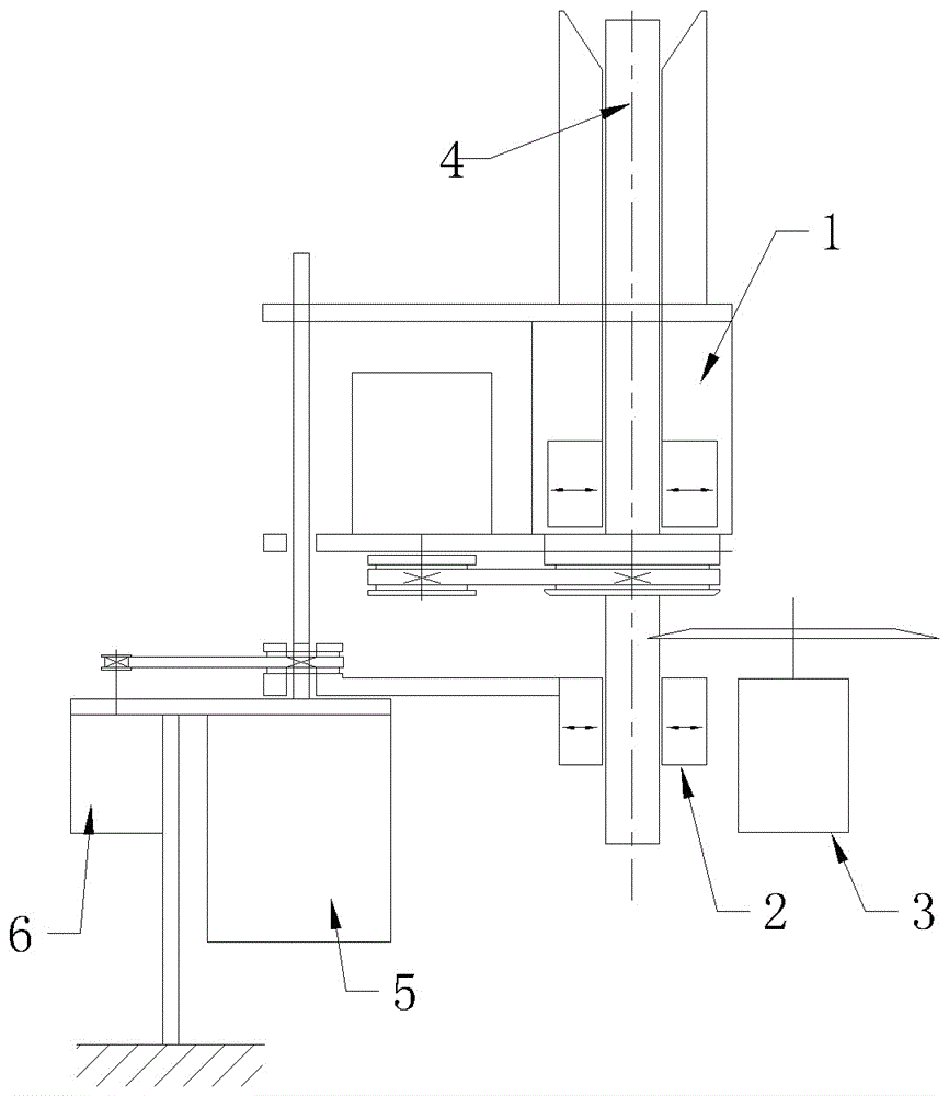
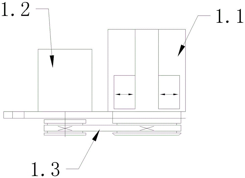
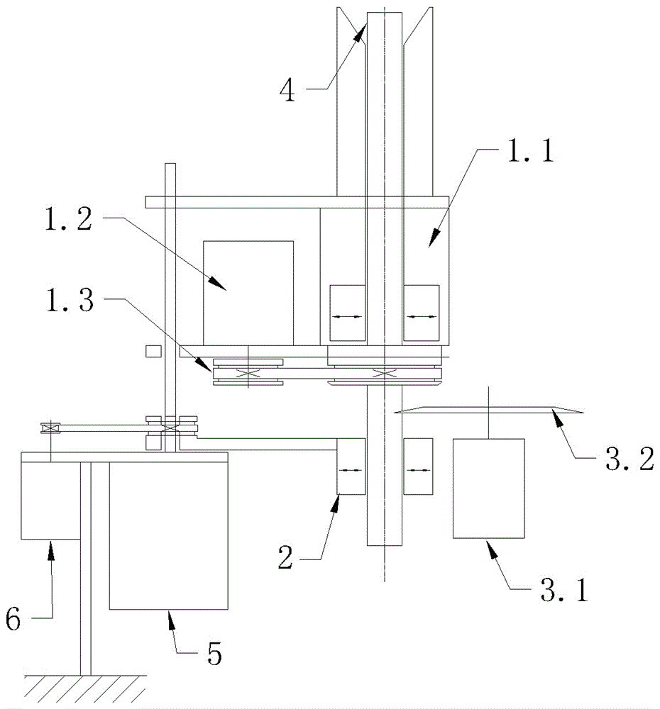
[0036] Such as Figure 1-13 As shown, a device for obtaining a cross section by rotary cutting of a bar includes a rotary clamping mechanism 1, a cutting end holding mechanism 2, a cutter mechanism 3 and a cutting and feeding mechanism. The rotary clamping mechanism 1 consists of a frame body, a rotatable The rotary chuck 1.1 arranged on the frame body, the drive motor 1.2 arranged on the frame body and the transmission mechanism connected between the drive motor 1.2 and the rotary chuck 1.1 are composed of the frame body and the clamping mechanism 2 at the cutting end. The cutting clip on the frame body is composed of the cutter mechanism 3. The cutter mechanism 3 is composed of a cutter drive motor 3.2 and a cutter 3.2 connected to the power output shaft of the cutter drive motor 3.2. The rotation axis of the cutter 3.2 and the rotation axis of the bar 4 are parall...


PUM


Abstract

The invention discloses a method for obtaining cross section through bar material rotary-type cutting and a device for obtaining the cross section through the bar material rotary-type cutting. The method adopts a manner that a bar material and a cutter both adopt active rotations; and, when cutting is performed, the rotary bar material and the rotary cutter contact each other to perform the cutting, and then a cross section is formed through the cutting. The device comprises a rotary clamping mechanism, a cut-off end holding and clamping mechanism, a cutter mechanism and a cutting feeding mechanism; the rotary clamping mechanism is composed of a rack body, a rotary clamp head which is rotatable and is disposed on the rack body, a drive motor disposed on the rack body, and a transmission mechanism connected between the drive motor and the rotary clamp head; and the cut-off end holding and clamping mechanism is composed of a rack body and a cut-off holding clamp disposed on the rack body, the cutter mechanism is composed of a drive motor and a cutter, the rotating axis of the cutter and the rotating axis of the bar material are parallel to each other, and the cutter is disposed at a height between the rotary clamp head and the cut-off holding clamp. The bar material rotating and cutter rotating manner is adopted, and the cross section obtained through the cutting can completely satisfy a high-precision analysis detection requirement.

Description

technical field [0001] The invention relates to an industrial processing method and device, in particular to a method and device for obtaining a cross-section through rotary cutting of a bar, and the cut cross-section of the bar is used for camera detection and analysis. Background technique [0002] In the field of product quality analysis and testing, especially in the detection and analysis of the physical shape of the cross-section of the object, the smaller the impact of the cutting tool on the detection cross-section, the better the quality of the detection cross-section, and the more accurate the imaging analysis data information. Especially in the detection of grooved filter rod cross-section in the tobacco industry, because the filter rod is relatively soft, it is easy to deform during the cutting process, and it is difficult to cut a good-quality cross-section to be detected in actual production. [0003] At present, the existing cutting method of fixing the filter...

Claims


Application Information

Patent Timeline
Patent Type & Authority Patents(China)
IPC IPC(8): B26D1/25B26D7/02B26D5/08
Inventor 张义熊景芳张广
Owner SHANGHAI PUSHUO AUTOMATION
Why Eureka
Try Eureka