Resultant high pressure relief air exhaust/supply valve

A technology of air supply valve and high pressure, which is applied in the direction of valve lift, valve details, valve device, etc., which can solve the problems of slow exhaust and no exhaust, and achieve the effects of tight sealing, reasonable structure and simplified production

Inactive Publication Date: 2012-12-05
杨鑫
View PDF0 Cites 2 Cited by
  • Summary
  • Abstract
  • Description
  • Claims
  • Application Information

AI Technical Summary

Problems solved by technology

[0003] The purpose of the present invention is to solve the problem that the small exhaust port exhausts slowly or does not exhaust when the high-pressure gas is released, and realizes that when the gas in the pipeline is at a pressure of 1.0MPa-2.5MPa, the sealing member of the small exhaust port is used The downward pull force generated by the cooperation of the large floating ball and the U-shaped connector can be opened smoothly, and the gas in the pipeline can be basically exhausted and cleaned within a unit of time, providing a new type that can prevent high-pressure gas from staying in Heli type high-pressure relief exhaust and supplementary air valve in the pipeline

Method used


Image

  • Resultant high pressure relief air exhaust/supply valve
  • Resultant high pressure relief air exhaust/supply valve
  • Resultant high pressure relief air exhaust/supply valve

Examples


Embodiment 1

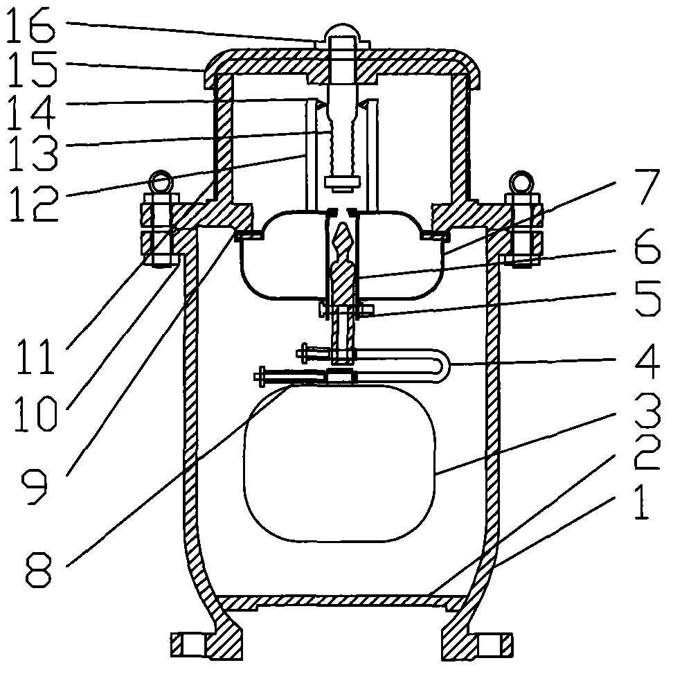
[0032] like figure 2As shown in the embodiment of high-pressure and small exhaust of Heli high-pressure exhaust and replenishment valve, when the large exhaust port is closed and the pressurized gas in the pipeline enters the valve body, the buoyancy of the large floating ball disappears and gravity is generated. At this time, the arrow-type dome seal that blocks the small exhaust port is subjected to two forces, one is the pipeline pressure pushing it up, and the other is the gravity of the large floating ball and the U-shaped connector that pulls it down. Since the resultant force pulling it down is greater than the pressure of the pipe pushing it up, the arrowhead dome seal is forced to pull away from the small vent, allowing high-pressure gas to exit the valve.

Embodiment 2

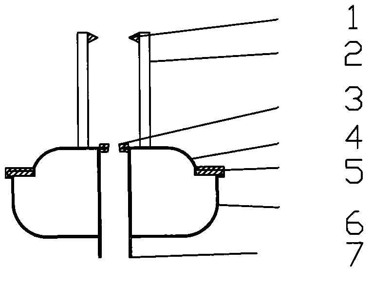
[0034] like image 3 As shown in the example, the Heli type high-pressure exhaust and supplementary air valve is implemented in large quantities. When the pipeline is filled with water for the first time, the gas in the pipeline first hits the energy dissipation plate, and then flows to the inner wall of the valve and enters the valve. Because the energy dissipation plate flows over one side Large area, small flow area on one side, large flow area, large gas flow, small flow area, small gas flow, so the gas will move the large floating ball and ball head flat seal from the side with large flow area Blow to the side with small flow area to generate oblique tension. At the same time, the pointed sliding ring forms an angle with the large thread at the lower part of the guide shaft and bites together to prevent the ball-type flat seal from moving upwards, achieving the anti-back effect and making the pipeline A large amount of gas is discharged smoothly.

Embodiment 3

[0036] Figure 4 It is a schematic diagram of the static state of the combined high-pressure discharge and air supply valve for gas injection. When the pipeline stops water supply, the ball-type flat seal after the large exhaust port is blocked, under the influence of gravity of itself, the large floating ball and the U-shaped connector. Under the action, the large exhaust port is smoothly opened and the gas is injected inward.


PUM


Abstract

The invention belongs to the technical field of water pipeline valves, and particularly relates to a resultant high pressure relief air exhaust / supply valve, which is characterized in that the split parts of the compound exhaust valve are compressed into a main body to form a whole, so as to solve the problems that the outline dimension is large, the appearance is irregular, and the making is complex; a big floating ball is combined with U-shaped connecting piece, and further solve the problems that the air exhaust is slow as a small exhaust port is over-small and the gravity force of the small floating ball can't pull open the sealed surface of the small exhaust port for air exhaust when the pressure reaches the peak value; the force produced by the big floating ball and connecting piece can amount to 4 to 45kg, the air exhaust area of the small exhaust port can amount to 13 to 200mm2; and by adopting the plane sealing of a ball head plane sealing element to replace the ball sealing, the problems that as the contact area of the ball sealing is small and the squeezing force is big, the ball is easily clamped, and the sealed surface is sometimes pulled broken during the falling process of the ball. The valve is used for air exhaust or air supply of the water pipeline, and is mainly characterized by completing exhaust of the high-pressure air in the long complex pipeline with big diameter and high drop, thereby bringing safety guarantee for the operation of the pipeline.

Description

1. Technical field [0001] The invention relates to the technical field of valves, and relates to a combined force type high-pressure discharge exhaust and replenishment valve for exhausting water supply pipelines to the outside or supplying air to the water supply pipelines inward. 2. Background technology [0002] At present, the commonly used devices for exhausting water pipes outward or supplying air inward to the pipeline are mainly as shown in the attached figure. The rolling shutter compound exhaust valve belongs to the double-body exhaust valve, and its structure includes an upper valve body and a lower valve. body and trace exhaust valve, which is provided with a large exhaust port and a sealing rubber ring on the upper valve body, with a nominal diameter, a floating ball protection bucket and a large floating ball on the lower valve body, and a small exhaust valve on the trace exhaust valve. Exhaust port and small floating ball; the disadvantage is that the external...

Claims


Application Information

Patent Timeline
Patent Type & Authority Applications(China)
IPC IPC(8): F16K31/20F16K1/36
Inventor 杨鑫杨玉文
Owner 杨鑫
Why Eureka
Try Eureka