A liquefied foundation treatment device increasing the gas content of underground water and a construction method

A technology for liquefying foundations and treatment devices, which is applied in infrastructure engineering, soil protection, construction, etc., can solve problems such as foundation structure damage, and achieve the effects of simple equipment, controllable construction quality, and low cost.

Inactive Publication Date: 2015-09-09
HOHAI UNIV
View PDF4 Cites 5 Cited by
  • Summary
  • Abstract
  • Description
  • Claims
  • Application Information

AI Technical Summary

Problems solved by technology

[0005] The present invention proposes a liquefaction foundation treatment device for increasing the gas content of groundwater, with the purpose of overcoming the defect that the existing underground aeration method and the groundwater level reduction method cause damage to the foundation structure.

Method used


Image

  • A liquefied foundation treatment device increasing the gas content of underground water and a construction method
  • A liquefied foundation treatment device increasing the gas content of underground water and a construction method
  • A liquefied foundation treatment device increasing the gas content of underground water and a construction method

Examples


Embodiment 1

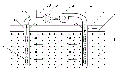
[0039] A construction method of a liquefaction foundation 1 treatment device for increasing the gas content of groundwater, such as figure 1 As shown, the construction method for a new construction site includes the following technical steps:

[0040] 1) According to the position and depth of the liquefied foundation 1, the part of the suction pipe 3 and the water inlet pipe 6 located in the liquefied foundation 1 is arranged with small holes 5;

[0041] 2) Wrap the suction pipe 3 and the water inlet pipe 6 with geotextile 4 and drive them into different positions of the liquefied foundation 1 respectively, and ensure that the holed parts of the suction pipe 3 and the water inlet pipe 6 are located in the liquefied foundation 1, and the suction pipe 3 and the The water inlet pipes 6 are respectively connected to the flexible pipes 7 above the surface covering layer 2;

[0042] 3) Connect the suction pipe 3, the water body gas content detection device 10, the external pump 8, ...

Embodiment 2

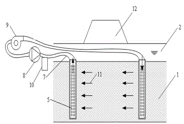
[0053] A construction method of a liquefaction ground treatment device for increasing the gas content of groundwater, such as figure 2 As shown, it is used for the construction method after the superstructure 12 of the liquefied foundation 1 is constructed.

[0054] The difference from Example 1 is that in step 2), the suction pipe 3 and the water inlet pipe 6 are wrapped with the geotextile 4 and driven into different positions of the liquefied foundation 1 respectively, and the holed parts of the suction pipe 3 and the water inlet pipe 6 are ensured to be uniform. Located in the liquefied foundation 1, the suction pipe 3 and the water inlet pipe 6 are respectively connected to the flexible pipe 7 in the surface covering layer 2; in step 3), the suction pipe 3, the gas content detection device 10 of the water body, the external suction pump 8, and the gas generating device 9 and the water inlet pipe 6 are sequentially connected through the flexible hose 7, and when forming a...


PUM


Abstract

The invention provides a liquefied foundation treatment device increasing the gas content of underground water and a construction method. The liquefied foundation treatment device comprises water pipes, geotechnical cloth, an external use water suction pump and a gas generation device. The two water pipes are water pipes with holes and include a water suction pipe and a water inlet pipe; the geotechnical cloth is wrapped around the outer layers of the water pipes. The parts with holes of the water suction pipe and the water inlet pipe are located in a liquefied foundation. The water suction pipe, the external use water suction pump, the gas generation device and the water inlet pipe are connected successively and form a closed water flow system together with the liquefied foundation. The lift of the external use water suction pump is greater than the length of the water suction pipe, so that deep underground water of the water suction pipe can be pumped out. The external use water suction pump pumps underground water in the liquefied foundation out; the pumped underground water is charged with bubbles by the gas generation device; then the water is fed to the liquefied foundation through the water inlet pipe. The liquefied foundation treatment device can reduce the saturation of the liquefied foundation without damaging the foundation structure and wasting resources.

Description

technical field [0001] The invention belongs to the technical field of civil engineering, and in particular relates to a liquefaction foundation treatment device and a construction method for increasing the gas content of groundwater. Background technique [0002] Liquefaction is one of the primary causes of site earthquake damage, and about 50% of foundation failures caused by earthquakes are caused by liquefaction. In recent years, my country's earthquake disasters have occurred continuously, among which sand liquefaction has caused serious damage to road pipelines, underground works, dams, etc., which has attracted widespread attention in the engineering field. [0003] The prevention and control of sand liquefaction mainly starts from two aspects: preventing the occurrence of sand liquefaction and preventing or alleviating uneven subsidence of buildings. Including rational selection of the site; taking measures such as vibrating, compacting, blasting, and compacting pil...

Claims


Application Information

Patent Timeline
Patent Type & Authority Applications(China)
IPC IPC(8): E02D3/10
Inventor 陈育民李文闻陈晨伟丁选明何森凯
Owner HOHAI UNIV
Why Eureka
Try Eureka