Compensating clutch with spacer elements

A clutch and component technology, applied in couplings, elastic couplings, mechanical equipment, etc., can solve problems such as high clutch consumption

Active Publication Date: 2018-12-07
ZF FRIEDRICHSHAFEN AG
View PDF7 Cites 0 Cited by
  • Summary
  • Abstract
  • Description
  • Claims
  • Application Information

AI Technical Summary

Problems solved by technology

Therefore, in a partially spring-loaded system, the disassembly of the clutch can only be carried out with great effort, since in particular at least one other component of the drive train must be lowered.

Method used


Image

  • Compensating clutch with spacer elements

Examples


Embodiment Construction

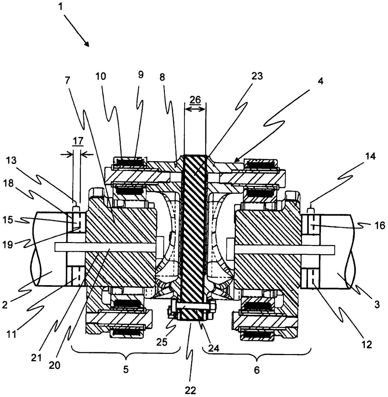
[0029] figure 1 The clutch device 1 is shown in longitudinal section. The clutch arrangement comprises first and second shafts 2 , 3 , which are connected to one another in a rotationally fixed and offset-compensating manner via an interposed compensating clutch 4 . Such clutch devices 1 are found in particular in drive trains of rail vehicles. The clutch device is arranged between the drive unit (not shown here) and the transmission unit. In this case, the drive unit is connected to a spring-mounted bogie of the rail vehicle, while the transmission unit is arranged axially on the axle without spring suspension. The shafts 2 , 3 of a drive unit or transmission unit (not shown here) to be connected to each other can thus be axially, radially and / or angularly offset / offset from one another.

[0030] In order to compensate axial, radial and / or angular offsets between the two shafts 2 , 3 , the compensating clutch 4 comprises a first and a second compensating unit 5 , 6 . The ...


PUM


Abstract

The invention relates to a compensating clutch for the non-rotatable and misalignment-compensated connection of two shafts, in particular for the drive side in a rail vehicle, comprising a first and a second compensating unit in a connection region are connected to each other and each have a fastening region on their sides facing away from each other for connection to a shaft provided for this purpose, at least one fastening region is configured such that the compensation unit can be connected with the shaft provided for this purpose in the axial direction in a first The axial lengths are fixed overlapping, a spacer element is arranged in the connecting region, which distances the two compensating units from each other in the axial direction by a second axial length which is greater than or equal to the first axial length length such that the compensating unit overlapping the shaft can be moved away from the shaft in the axial direction by at least a first axial length in order to remove the compensating clutch when the spacer element is removed. The invention also relates to a clutch arrangement with such a compensating clutch.

Description

technical field [0001] The invention relates to a compensating clutch and a clutch device. Background technique [0002] Compensating clutches are used in drive engineering, which connect two shafts in a rotationally fixed manner and offset-compensated. Such compensating clutches are not switchable, but, apart from torque transmission, serve primarily to compensate axial, radial and / or angular misalignments between two shafts to be connected to each other. [0003] EP 0632210 A1 discloses a compensating clutch in the form of a circular tooth clutch. The misalignment compensation here takes place by means of two spherical outer toothings of a connecting part arranged between the first and second clutch parts, which each mesh with an inner toothing of a correspondingly assigned clutch part. [0004] As an alternative, for example, DE 10 2012 002 660 A1 discloses a compensating clutch designed as an elastic torsion clutch. In this case, the misalignment compensation is not c...

Claims


Application Information

Patent Timeline
Patent Type & Authority Patents(China)
IPC IPC(8): F16D3/70
CPCF16D3/74F16D3/78F16D3/70
Inventor 科里斯托弗·萨切尔西蒙·普罗布斯特
Owner ZF FRIEDRICHSHAFEN AG
Why Eureka
Try Eureka