
Laser transmission target and laser alignment method

A laser transmission and target technology, applied in the laser field, can solve the problem of not being able to use multi-target synchronous collimation, and achieve the effect of convenient equipment collimation, reducing operation steps and improving work efficiency

Active Publication Date: 2021-08-31
INST OF HIGH ENERGY PHYSICS CHINESE ACAD OF SCI
View PDF0 Cites 0 Cited by
  • Summary
  • Abstract
  • Description
  • Claims
  • Application Information

AI Technical Summary

Problems solved by technology

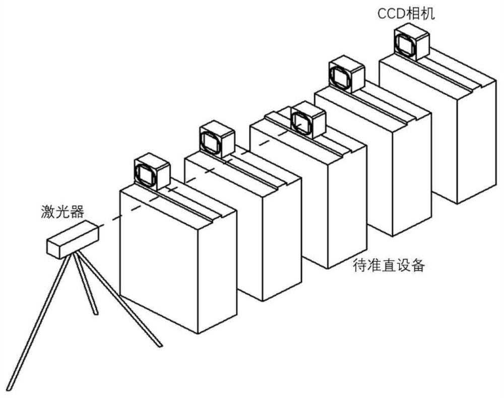
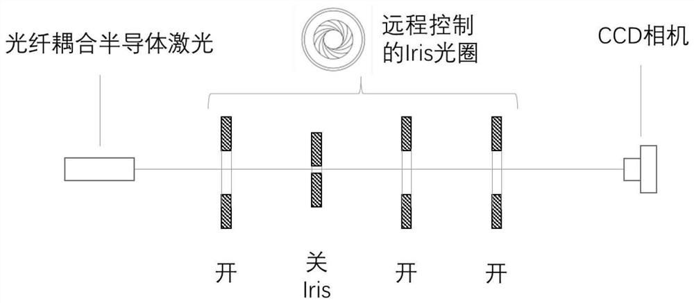
Only one device can be collimated at a time during laser collimation, and it cannot be used for simultaneous collimation of multiple targets

Method used


Image

  • Laser transmission target and laser alignment method
  • Laser transmission target and laser alignment method
  • Laser transmission target and laser alignment method

Examples


Embodiment Construction

[0062] The present application will be described in further detail below with reference to the drawings and embodiments, but not limited thereto.

[0063] Such as Figure 5 As shown, there is a "V" shaped prism inside the laser transmission target of the present invention, and the "V" shaped prism has two vertical planes M1 and M6 which are the incident surface and the outgoing surface respectively, and the surface is coated with an anti-reflection film; There are 4 slopes M2, M3, M4, M5, the surface of M2 is coated with semi-transparent and semi-reflective film, the surface of M3, M4, M5 is coated with high reflection film, the angle between the slope and the vertical plane M1, M2 is 45° °, the inclined plane M2 is perpendicular to M5, and M3 is perpendicular to M4.

[0064] The internal light path part of the whole target such as Figure 9 As shown, glue the slope of the right-angled triangular prism with the slope M2 of the "V"-shaped prism (the slope of the right-angled ...


PUM


Abstract

The invention discloses a laser transmission target and a laser alignment method. The laser transmission target of the present invention is characterized in that, comprises " V " font prism, rectangular parallelepiped prism, right angle triangular prism and CCD camera; The vertical plane M1, M6 that this " V " font prism is opposite is incident surface and exit surface respectively, and this The four slopes of the "V"-shaped prism are respectively marked as M2, M3, M4, and M5, wherein the vertical plane M1 intersects with the inside slope M2 and the outside slope M3 respectively, and the vertical plane M6 intersects with the inside slope M5 and the outside slope M4 respectively. Intersect; the slope of the rectangular prism is parallel to the slope M2 of the "V" prism, a plane of the cuboid prism is fixed parallel to the M6 ​​surface of the "V" prism, and the CCD camera is used to receive the light beam emitted from the slope M5 . The invention realizes the online synchronous alignment and real-time displacement monitoring of the equipment.

Description

technical field [0001] The invention belongs to the technical field of lasers, and relates to a laser transmission target and a laser alignment method. Background technique [0002] Due to its high brightness and good directivity, laser can be used for collimation of equipment. The principle of laser alignment: take the line connecting the energy centers of the laser beam as the reference line, the laser beam is irradiated on the target, the spot detector inside the target measures the position information of the target relative to the laser reference line, and the target is installed on the On the measuring device, the relative positional relationship between the devices can be obtained. For the alignment of multiple devices, laser alignment based on conventional targets uses the method of target movement measurement, that is, the target is placed on the current device to be aligned, the position of the device relative to the laser beam is measured, and then the target is ...

Claims


Application Information

Patent Timeline
Patent Type & Authority Patents(China)
IPC IPC(8): G01B11/00G02B5/04G02B27/10
CPCG01B11/00G02B5/04G02B27/10
Inventor 卢尚王铜董岚梁静王小龙门玲鸰罗涛柯志勇何振强马娜李波韩圆颖闫路平
Owner INST OF HIGH ENERGY PHYSICS CHINESE ACAD OF SCI
Learn More