Automatic adjustment method of grinding wheel position of drill edge grinder, its device and driving device

An automatic adjustment device and automatic adjustment technology are applied to the parts of boring machine/drilling machine, drilling tool accessories, drilling/drilling equipment, etc., which can solve the problems of inconvenient, difficult to grasp the accuracy, and hinder the working efficiency of the grinding machine. Achieve the effect of improving accuracy and improving accuracy

Active Publication Date: 2016-09-28
PHOWN ENTERPRISE
View PDF7 Cites 0 Cited by
  • Summary
  • Abstract
  • Description
  • Claims
  • Application Information

AI Technical Summary

Problems solved by technology

[0004] In the prior art, in order to correct the reference position of the drill bit facet, the position of the grinding wheel of the drill bit grinder is manually adjusted, so that the grinding wheel of the grinder can properly regrind the drill bit facet, but due to the diameter of the drill bit facet It is only about 0.1 to 1.0mm, so it is not convenient to manually adjust the position of the grinding wheel of the drill grinder, and the accuracy is not easy to grasp, and it also hinders the work efficiency of the grinder, which needs to be improved urgently

Method used


Image

  • Automatic adjustment method of grinding wheel position of drill edge grinder, its device and driving device
  • Automatic adjustment method of grinding wheel position of drill edge grinder, its device and driving device
  • Automatic adjustment method of grinding wheel position of drill edge grinder, its device and driving device

Examples


Embodiment Construction

[0040] first look figure 2 Shown, reveals the flowchart of the preferred embodiment of the present invention, and coordinates Figure 1a , Figure 1d , image 3 , Figure 4 and Figure 8 The method for automatically adjusting the position of the grinding wheel of the drill grinder of the present invention includes the following implementation steps:

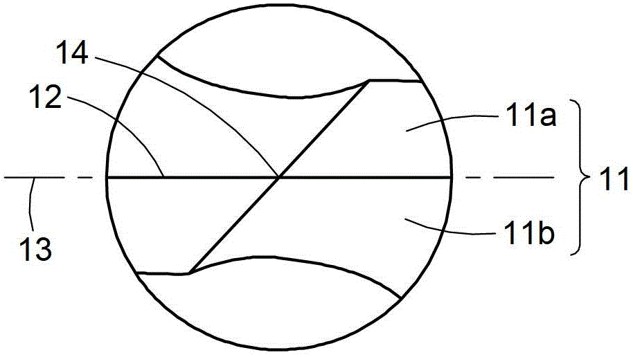
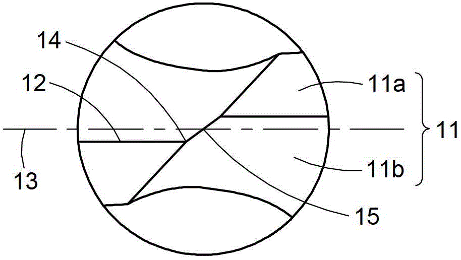
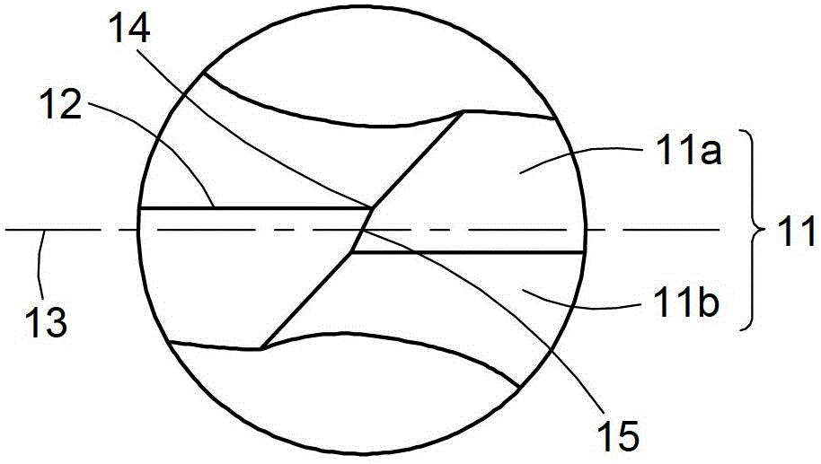
[0041] In step S11, a charge-coupled device 41 is used to detect a bevel line 12 offset v of a drill face 11 (such as Figure 8 and Figure 1d shown). Wherein the drill edge face 11 comprises a first edge face 11a and a second edge face 11b (such as Figure 1a shown). The edge line 12 is located at the junction of the first edge surface 11a and the second edge surface 11b, and the offset v of the edge edge line 12 is the deviation between the edge edge line 12 and a reference line 13 of the edge edge. displacement (such as Figure 1d shown). Furthermore, the charge-coupled device 41 may include a CCD imaging unit, which...


PUM


Abstract

The invention provides an automatic grinding wheel position adjusting method for a drill lip grinder. The method includes the steps: detecting the cutting edge angle line offset of a bit face by a charge coupling element; driving a cam by a driver and further driving a grinding wheel to axially shift to a correction position along a grinding wheel spindle of the grinding wheel. The grinding wheel at the correction position is used for grinding the bit face and further compensating the cutting edge angle line offset. The invention further provides an automatic grinding wheel position adjusting device for the drill lip grinder, and provides a grinding wheel position driving device for the drill lip grinder, wherein the adjusting device is needed by implementing the method, and the driving device is used for removing the charge coupling element.

Description

technical field [0001] The invention relates to the technical field of drill grinders, in particular to a method for automatically adjusting the position of a grinding wheel of a drill grinder and a device thereof, and a driving device used in the method for automatically adjusting the position of a grinder of the drill grinder. Background technique [0002] It is well known that a micro drill bit is a drilling tool with a blade surface diameter of only about 0.1 to 1.0 mm, and has been widely used in drilling operations for printed circuit boards. After repeated use of the drill bit, its blade surface is easy to wear and lose drilling accuracy; in order to prolong the service life of the drill bit blade surface, the practice at this stage is to use a grinder to regrind the worn drill bit edge surface, and use The drill facet returns to the state available for drilling to the correct hole diameter accuracy. Before the drill bit is reground by a grinding machine, it is neces...

Claims


Application Information

Patent Timeline
Patent Type & Authority Patents(China)
IPC IPC(8): B24B3/24
Inventor 姚志金
Owner PHOWN ENTERPRISE
Why Eureka
Try Eureka