Multi-system flooded evaporator
A flooded evaporator and multi-system technology, applied in the field of multi-system flooded evaporators, can solve the problems of refrigerant waste, difficulty in independent operation, increased use costs, etc., achieve uniform heat exchange, improve refrigeration effect, Use flexible effects
- Summary
- Abstract
- Description
- Claims
- Application Information
AI Technical Summary
Problems solved by technology
Method used
Image
Examples
Embodiment 1
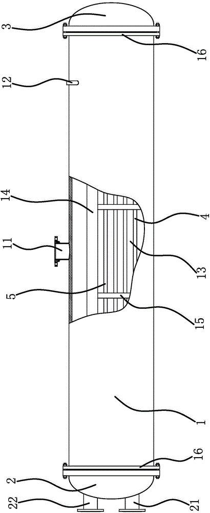
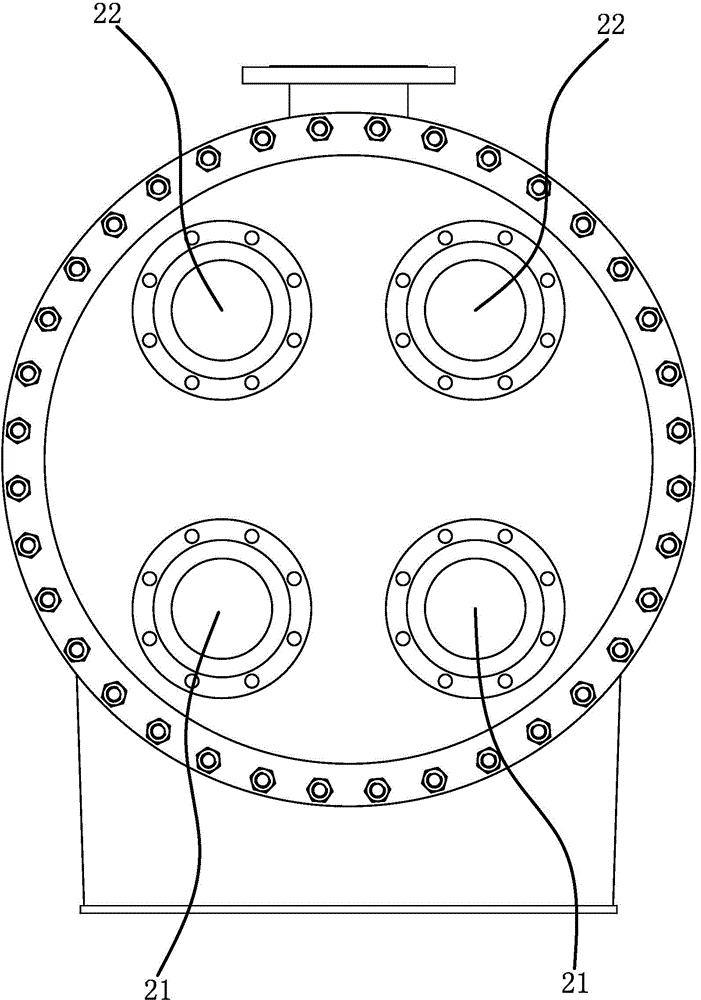
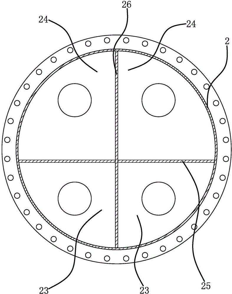
[0033] Such as figure 1 , figure 2 , image 3 As shown, a multi-system flooded evaporator includes a cylinder body 1, a front pipe box 2 and a rear pipe box 3, the front pipe box 2 and the rear pipe box 3 are fixedly connected to both ends of the cylinder body 1 respectively, and the cylinder body 1 is provided with a steam outlet 11 and two liquid inlets 12. The multi-system dry evaporator also includes two groups of refrigeration circuits, each group of refrigeration circuits includes a water inlet pipe 21 and a water inlet chamber located in the front pipe box 2 23 and the water outlet chamber 24, the cooling chamber 13 located in the cylinder body 1, and the return chamber 31 located in the rear tube box 3, the cooling chamber 13 is fixedly connected with a number of incoming heat exchange tubes 4 and a number of return flow heat exchange tubes 5, The water inlet pipe 21 is connected with the water inlet chamber 23, the water outlet pipe 22 is connected with the water o...
Embodiment 2
[0037] The structure of this multi-system flooded evaporator is basically the same as that of Embodiment 1, the difference is that Figure 6 , Figure 7 , Figure 8 , Figure 9 As shown, there are three groups of refrigeration circuits, two front longitudinal partitions 26, the water inlet chamber 23 and the water outlet chamber 24 are located between the front longitudinal partition 26 and the inner wall of the cylinder 1 and between two adjacent front longitudinal partitions 26, and the shell side There are two partitions 14, the cooling chamber 13 is located between the shell-side partition 14 and the inner wall of the cylinder 1 and between two adjacent shell-side partitions 14, there are three liquid inlets 12, and the three liquid inlets 12 are connected with The three refrigeration chambers 13 correspond one to one. There are two rear longitudinal diaphragms 32, and the return cavity 31 is located between the rear longitudinal diaphragm 32 and the inner wall of the c...
PUM
 Abstract
Description
Claims
Application Information
 - R&D
- Intellectual Property
- Life Sciences
- Materials
- Tech Scout
- Unparalleled Data Quality
- Higher Quality Content
- 60% Fewer Hallucinations
Browse by: Latest US Patents, China's latest patents, Technical Efficacy Thesaurus, Application Domain, Technology Topic, Popular Technical Reports.
© 2025 PatSnap. All rights reserved.Legal|Privacy policy|Modern Slavery Act Transparency Statement|Sitemap|About US| Contact US: help@patsnap.com


