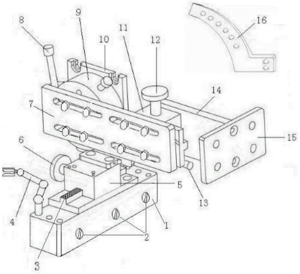
Steam turbine differential expansion and shaft displacement instrument portable verifying table
A technology of shaft displacement and calibration table, which is applied to instruments, mechanical devices, mechanical measuring devices, etc., can solve problems such as affecting the calibration accuracy of the instrument, time-consuming, labor-consuming, and occupation of the pins of the instrument bracket, so as to improve work efficiency. Effect
- Summary
- Abstract
- Description
- Claims
- Application Information
AI Technical Summary
Problems solved by technology
Method used
Image
Examples
Embodiment 1
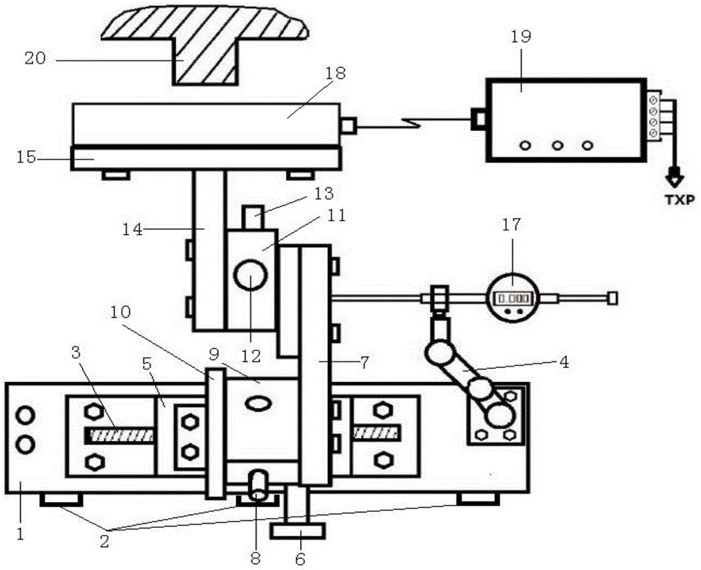
[0030] like figure 2 As shown, when calibrating the differential expansion instrument of the steam turbine:
[0031] 1.1. Install the differential expansion instrument 18 to be verified with the fixed module 15 of the differential expansion instrument;
[0032] 1.2. Place the portable calibration table on the cylinder block of the steam turbine, adjust the gap between the instrument to be calibrated and the rotor cam 20 through the rotary table 9 and the displacement table 11, close the locking switch 2, and fix the calibration table ;
[0033] 1.3. Fix the dial gauge 17 on the calibration platform through the dial gauge fixing arm 4, and adjust the dial gauge to keep it level with the translation platform 5.
[0034] 1.4. Rotate the translation knob 6 to simulate the relative expansion of the rotor and the cylinder and the axial displacement of the rotor, and read the relative displacement through the dial indicator;
[0035] 1.5. According to the recorded data, it is jud...
Embodiment 2
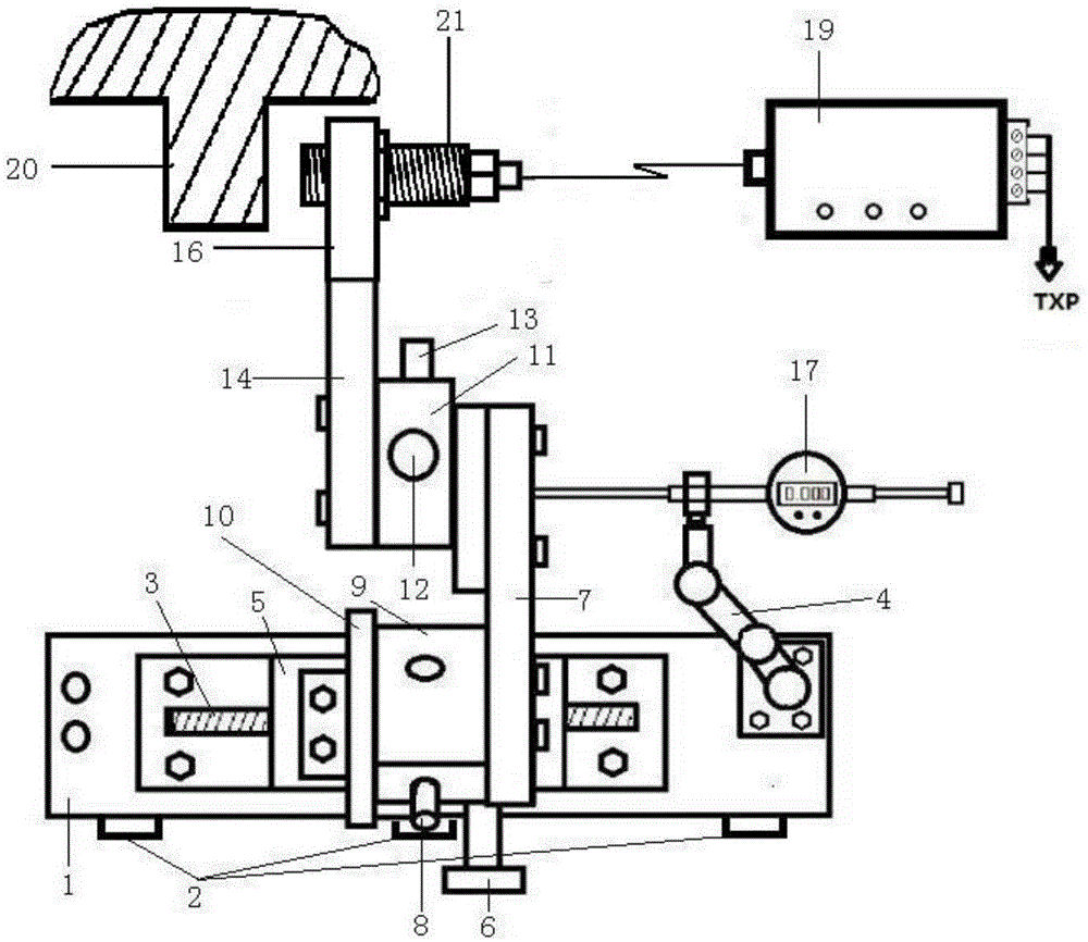
[0037] like image 3 As shown, to calibrate the shaft displacement instrument of the steam turbine:
[0038] 2.1. The shaft displacement meter 21 to be verified is installed through the shaft displacement meter fixing module 16, and six shaft displacement meters can be installed at the same time;
[0039] 2.2. Place the portable calibration table on the cylinder block of the steam turbine, adjust the gap between the instrument to be calibrated and the rotor cam through the rotary table 9 and the displacement table 11, close the locking switch 2, and fix the calibration table;
[0040] 2.3. Fix the dial gauge 17 on the calibration platform through the dial gauge fixing arm 4, and adjust the dial gauge to keep it level with the translation platform 5.
[0041] 2.4. Rotate the translation knob 6 to simulate the relative expansion of the rotor and the cylinder and the axial displacement of the rotor, and read the relative displacement through the dial indicator.
[0042] 2.5. A...
PUM
 Abstract
Description
Claims
Application Information
 - R&D
- Intellectual Property
- Life Sciences
- Materials
- Tech Scout
- Unparalleled Data Quality
- Higher Quality Content
- 60% Fewer Hallucinations
Browse by: Latest US Patents, China's latest patents, Technical Efficacy Thesaurus, Application Domain, Technology Topic, Popular Technical Reports.
© 2025 PatSnap. All rights reserved.Legal|Privacy policy|Modern Slavery Act Transparency Statement|Sitemap|About US| Contact US: help@patsnap.com


