
Laser image real time monitoring method measuring relative displacement

A technology of real-time monitoring and relative displacement, applied in the direction of measuring devices, optical devices, instruments, etc., can solve the problems of being unable to adapt to the safety monitoring of large-scale transportation infrastructure, easily threatening the safety of detection personnel, and backward safety monitoring methods, etc. Interfering with vehicle operation and engineering construction, ensuring construction safety, and strong anti-interference ability

Inactive Publication Date: 2015-09-09
TIANJIN UNIV
View PDF8 Cites 18 Cited by
  • Summary
  • Abstract
  • Description
  • Claims
  • Application Information

AI Technical Summary

Problems solved by technology

The reason is that for a long time, the safety monitoring methods of the above-mentioned projects have been relatively backward. The instruments used include spirit levels, spirit levels, total stations and theodolites, etc., and the methods of manual regular inspection and data comparison are mainly used.
This traditional method has low precision, many interference factors, time-consuming and labor-intensive, and is likely to threaten the safety of inspectors. Therefore, traditional monitoring methods can no longer meet the needs of large-scale transportation infrastructure safety monitoring.

Method used


Image

  • Laser image real time monitoring method measuring relative displacement
  • Laser image real time monitoring method measuring relative displacement
  • Laser image real time monitoring method measuring relative displacement

Examples


Embodiment Construction

[0017] In order to further understand the invention content, characteristics and effects of the present invention, the following examples are given, and detailed descriptions are as follows in conjunction with the accompanying drawings:

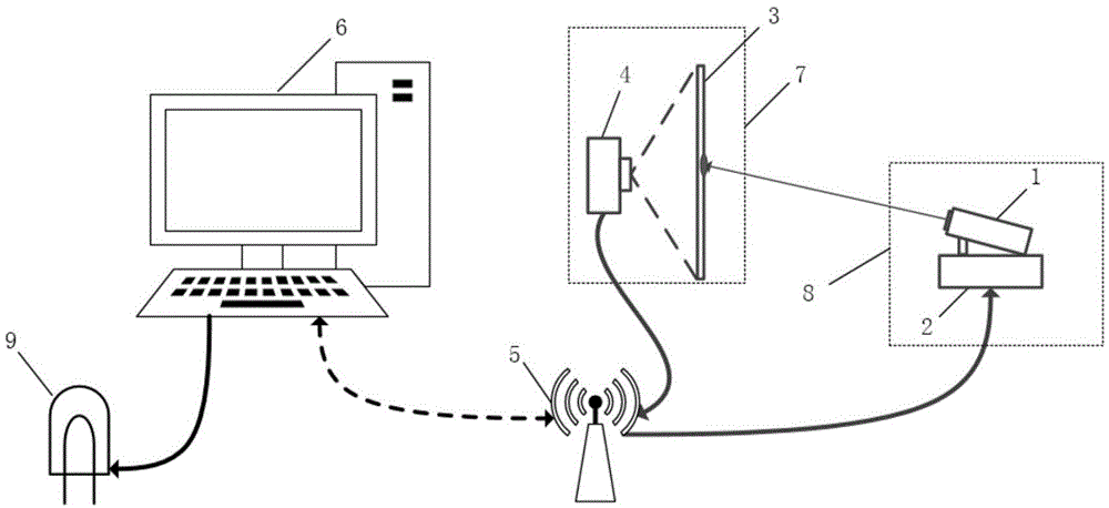
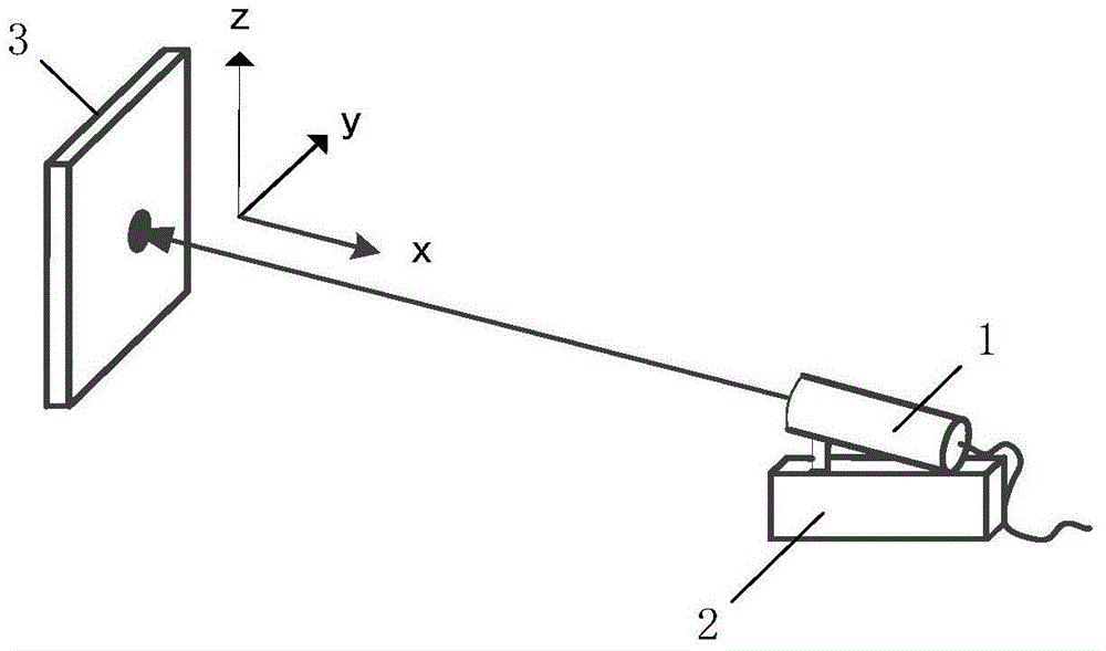
[0018] see Figure 1 to Figure 5 , a laser image real-time monitoring method for measuring relative displacement, the optical reference module 8 is installed on the structure to be monitored, and the laser image acquisition module 7 is installed on the reference surface, the optical reference module 8 includes a two-dimensional rotating table 2 and The laser transmitter 1 fixed on it, the two-dimensional rotary table 2 is driven by a driver and a reducer assembly; the laser image acquisition module 7 includes a filter transmission screen 3 and a CCD camera 4, and the CCD camera 4 The field of view is parallel to the filter transmission screen 3, and the filter transmission screen 3 is located at the focal length position of the CCD camera 4; ...


PUM


Abstract

The invention discloses a laser image real time monitoring method measuring relative displacements; an optics reference module is arranged on a monitored structure; a laser image acquisition module is arranged on a reference surface; the optics reference module comprises a two-dimension rotary table and a laser emitter arranged on the rotary table; the two-dimension rotary table is driven by a driver and a speed reducer; the laser image acquisition module comprises a filter transmission screen and a CCD camera; a visual field of the CCD camera is parallel to the filter transmission screen positioned in a focus position of the CCD camera; the laser emitted by the laser emitter hits on the filter transmission screen; the CCD camera carries out image data acquisition for laser spots on the filter transmission screen, and transfers the image data to a monitor host in real time; the monitor host firstly calculates the displacements of the monitored structure, and determines whether the displacement of the monitored structure exceeds a safety threshold or not, if yes, controlling an alarmer to send alarms. The laser image real time monitoring method can realize remote, automatic and 24-hour real time monitoring.

Description

technical field [0001] The invention relates to a method for safety monitoring of large-scale traffic infrastructure, in particular to a method for real-time monitoring of laser images for measuring relative displacement. Background technique [0002] With the increasing comprehensive national strength of our country and the rapid development of transportation, various types of bridges, culverts and tunnels and other large-scale infrastructure are becoming more and more important in railway and highway traffic engineering, and their safety inspection is essential. The safety monitoring items of large-scale transportation infrastructure mainly include the settlement and inclination of the engineering matrix, the influence of concrete creep on the long-term deflection, the damage to the structure caused by geological disasters and floods, and the structural deformation caused by internal stress. However, in recent years, engineering accidents of large-scale transportation infr...

Claims


Application Information

Patent Timeline
Patent Type & Authority Applications(China)
IPC IPC(8): G01B11/02G01B11/16
Inventor 裘祖荣陈哲刘佳琛胡文川
Owner TIANJIN UNIV
Learn More