Machine vision-based twisted pair pitch measuring method
A measurement method and machine vision technology, applied in measurement devices, instruments, optical devices, etc., can solve the problems of high labor intensity, inability to real-time automatic detection of twisted pairs, and large detection errors.
- Summary
- Abstract
- Description
- Claims
- Application Information
AI Technical Summary
Problems solved by technology
Method used
Image

Examples
Embodiment Construction
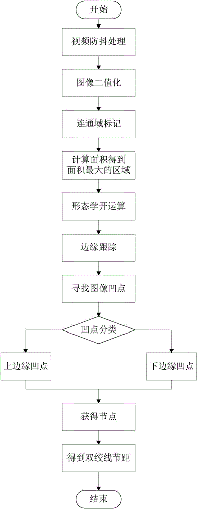
[0038] Below in conjunction with accompanying drawing, the twisted pair pitch measuring method based on machine vision of the present invention is described in detail:
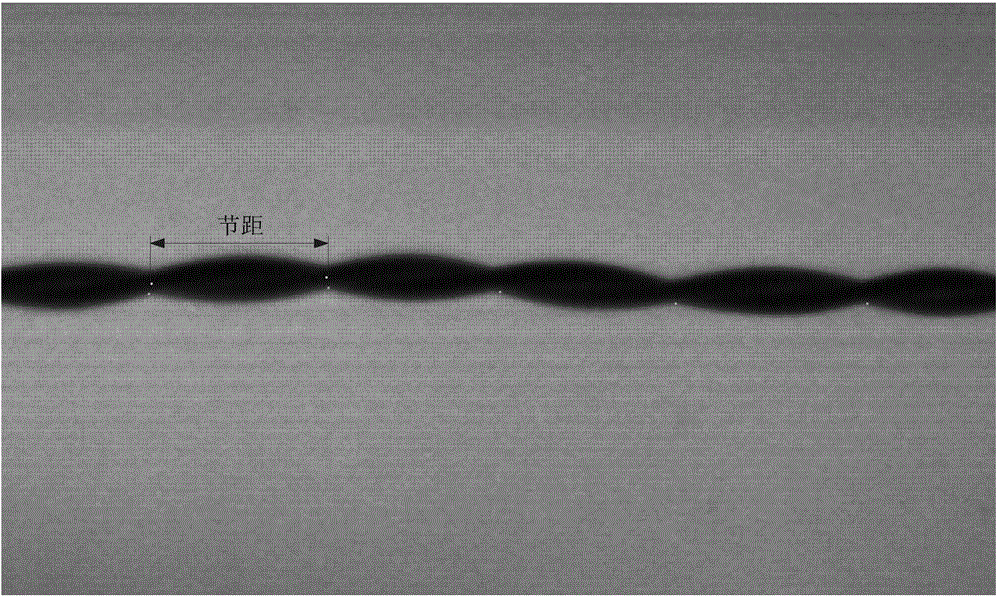
[0039] Step 1: Use the camera to collect twisted pair images;
[0040] Step 2: Perform anti-shake processing on the video in step 1. The algorithm is based on feature matching and affine transformation to obtain each frame of image after anti-shake processing;
[0041] Step 2-1: read the previous frame image as the reference image, and extract scale-invariant feature points;
[0042] Step 2-2: Read the current frame and calculate the feature points, use the affine transformation model to register with the reference image, and use the registered image as the new current frame.
[0043] Step 3: Binarize the image obtained in step 2 according to the set gray threshold to obtain a binary image;
[0044] Step 3-1: Set the gray threshold in the binarization process to be the gray threshold obtained by using the ma...
PUM
 Abstract
Description
Claims
Application Information