
LED light heat dissipation structure

A heat dissipation structure and technology of LED lamps, which are applied in lighting and heating equipment, cooling/heating devices for lighting devices, lighting devices, etc. The effect of service life

Active Publication Date: 2018-04-20
东莞市闻誉实业有限公司
View PDF8 Cites 0 Cited by
  • Summary
  • Abstract
  • Description
  • Claims
  • Application Information

AI Technical Summary

Problems solved by technology

[0006] However, the heat dissipation of electronic devices in the prior art is basically completed through the heat conduction between the heat conductor and the heat sink, and the heat dissipation effect is not very ideal, so it is necessary to provide a new heat dissipation device

Method used


Image

  • LED light heat dissipation structure
  • LED light heat dissipation structure
  • LED light heat dissipation structure

Examples


Embodiment Construction

[0023] In order to make the above objects, features and advantages of the present invention more comprehensible, specific implementations of the present invention will be described in detail below in conjunction with the accompanying drawings. In the following description, numerous specific details are set forth in order to provide a thorough understanding of the present invention. However, the present invention can be implemented in many other ways different from those described here, and those skilled in the art can make similar improvements without departing from the connotation of the present invention, so the present invention is not limited by the specific embodiments disclosed below.

[0024] In describing the present invention, it should be understood that the terms "center", "longitudinal", "transverse", "length", "width", "thickness", "upper", "lower", "front", " Back", "Left", "Right", "Vertical", "Horizontal", "Top", "Bottom", "Inner", "Outer", "Clockwise", "Counte...


PUM


Abstract

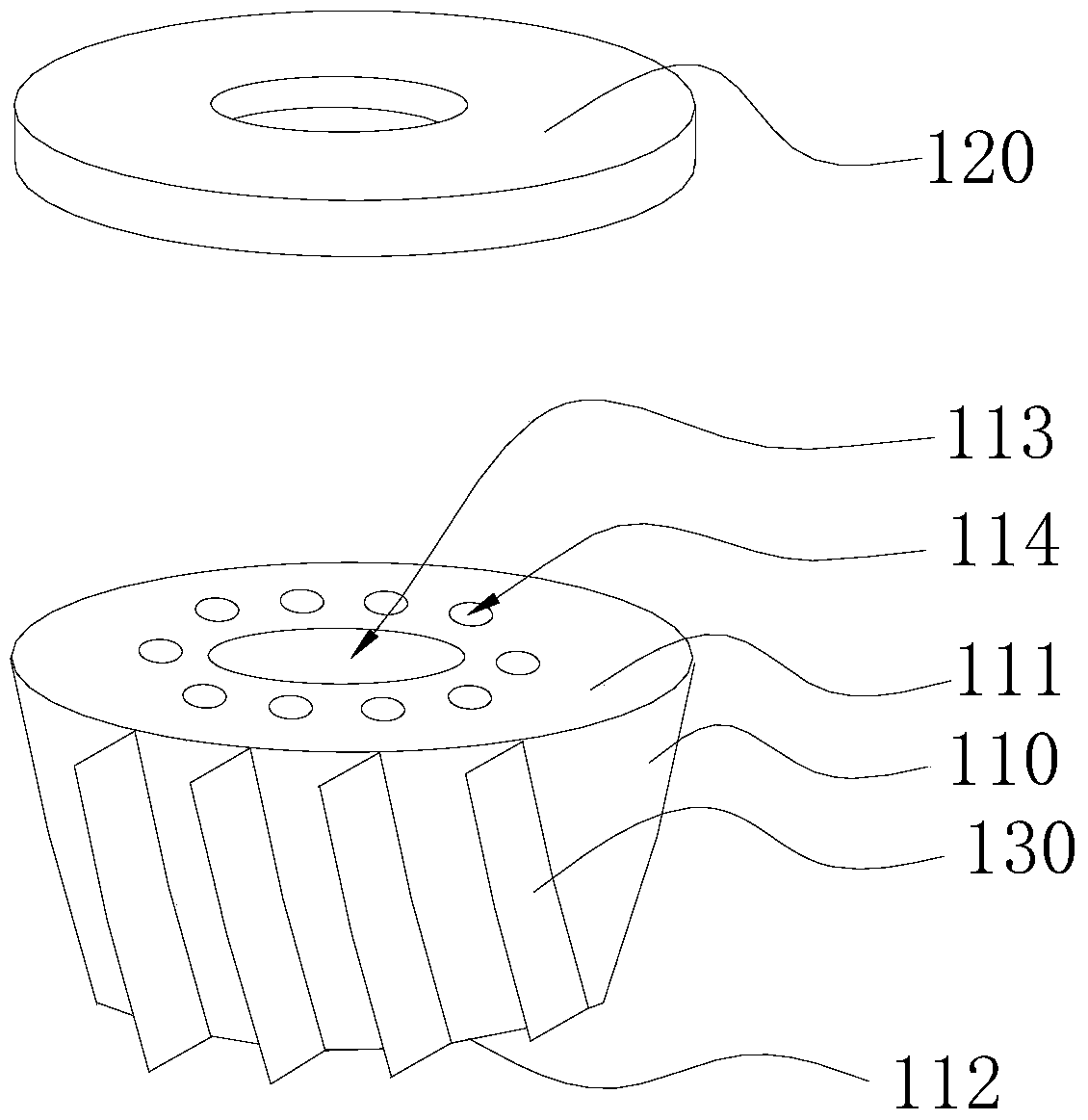
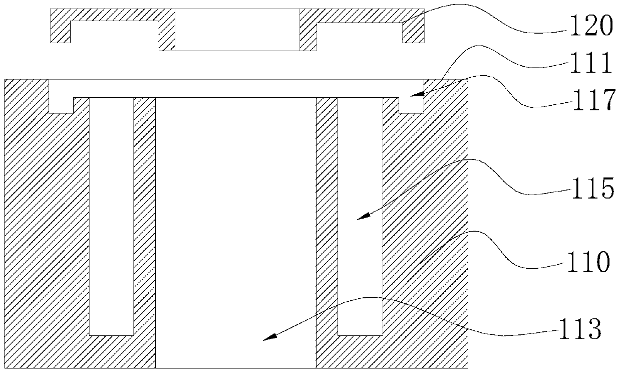
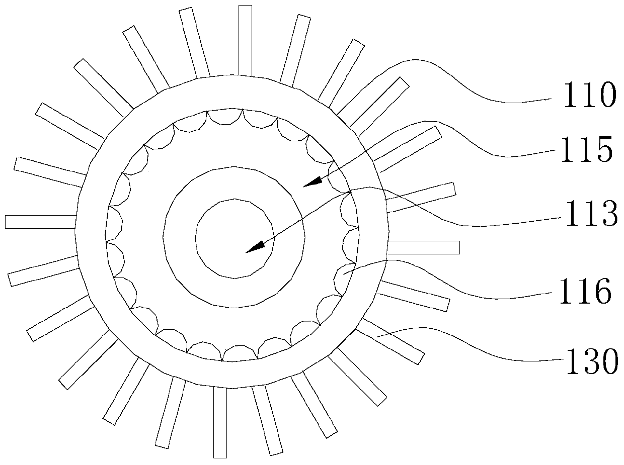
An LED lamp heat radiation structure includes a heat radiation shell, a cover body and cooling fins. The heat radiation shell includes a first surface and a second surface arranged opposite to the first surface, and is provided with a through hole and a plurality of blind holes which surround the periphery of the through hole, a first end of the through hole is located in a middle position of the first surface of the heat radiation shell, a second end is located on the second surface of the heat radiation shell, and heat radiation liquid is filled in the blind holes; the cover body is fixedly connected to the heat radiation shell, and the cover body and the blind holes form a closed region; and the cooling fins are radially and uniformly arranged in the periphery of the heat radiation shell. The abovementioned LED lamp heat radiation structure is provided with the plurality of blind holes on an annular circumferential wall, the heat radiation liquid is filled in the blind holes, heat generated by an LED lamp is uniformly absorbed by the heat radiation liquid, and a circumstance that a large amount of heat cannot be radiated in a short time due to small heat capacity, thereby causing damage to the LED lamp, is avoided.

Description

technical field [0001] The present invention relates to the technical field of heat dissipation, in particular to a heat dissipation structure of an LED lamp. Background technique [0002] With the vigorous development of high technology, electronic products are becoming more and more intelligent and complex, the volume of electronic components tends to be miniaturized, and the density per unit area is also getting higher and higher. The direct impact of this situation is that electronic products generate more and more heat during operation. If there is no good heat dissipation method to remove the heat generated by the electrons, these excessively high temperatures will lead to electron ionization and thermal stress in the electronic components, resulting in a decrease in overall stability and shortening the life of the electronic components themselves. Therefore, how to remove these heats to avoid overheating of electronic components has always been a problem that cannot ...

Claims


Application Information

Patent Timeline
Patent Type & Authority Patents(China)
IPC IPC(8): H01L33/64F21V29/56F21Y115/10
CPCH01L33/64
Inventor 叶伟炳
Owner 东莞市闻誉实业有限公司
Learn More