Terminal pin plugging device

A pin insertion device and pin insertion technology are applied in the assembly/disassembly of contacts, contact manufacturing, electrical components, etc., and can solve the problems that cannot meet the requirements of miniaturization and high-density terminal processing.

Inactive Publication Date: 2015-09-09
SUZHOU HANCHUAN CO LTD AKA HARMONTRONICS
View PDF6 Cites 4 Cited by
  • Summary
  • Abstract
  • Description
  • Claims
  • Application Information

AI Technical Summary

Problems solved by technology

Obviously, this traditional method of manually inserting terminals into the workpiece cannot meet the current processing requirements for miniaturized and high-density terminals.

Method used


Image

  • Terminal pin plugging device
  • Terminal pin plugging device
  • Terminal pin plugging device

Examples


Embodiment Construction

[0020] In order to better understand the technical solution of the present invention, a preferred embodiment provided by the present invention will be described in detail below in conjunction with the accompanying drawings.

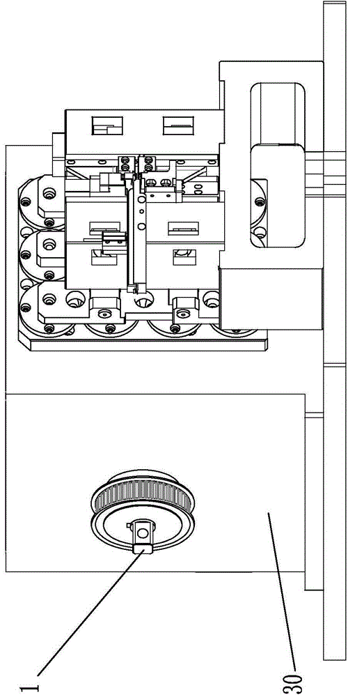
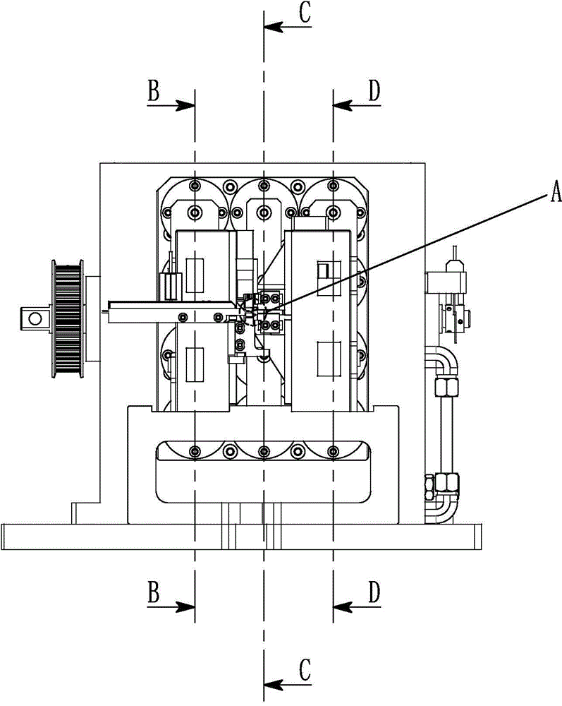
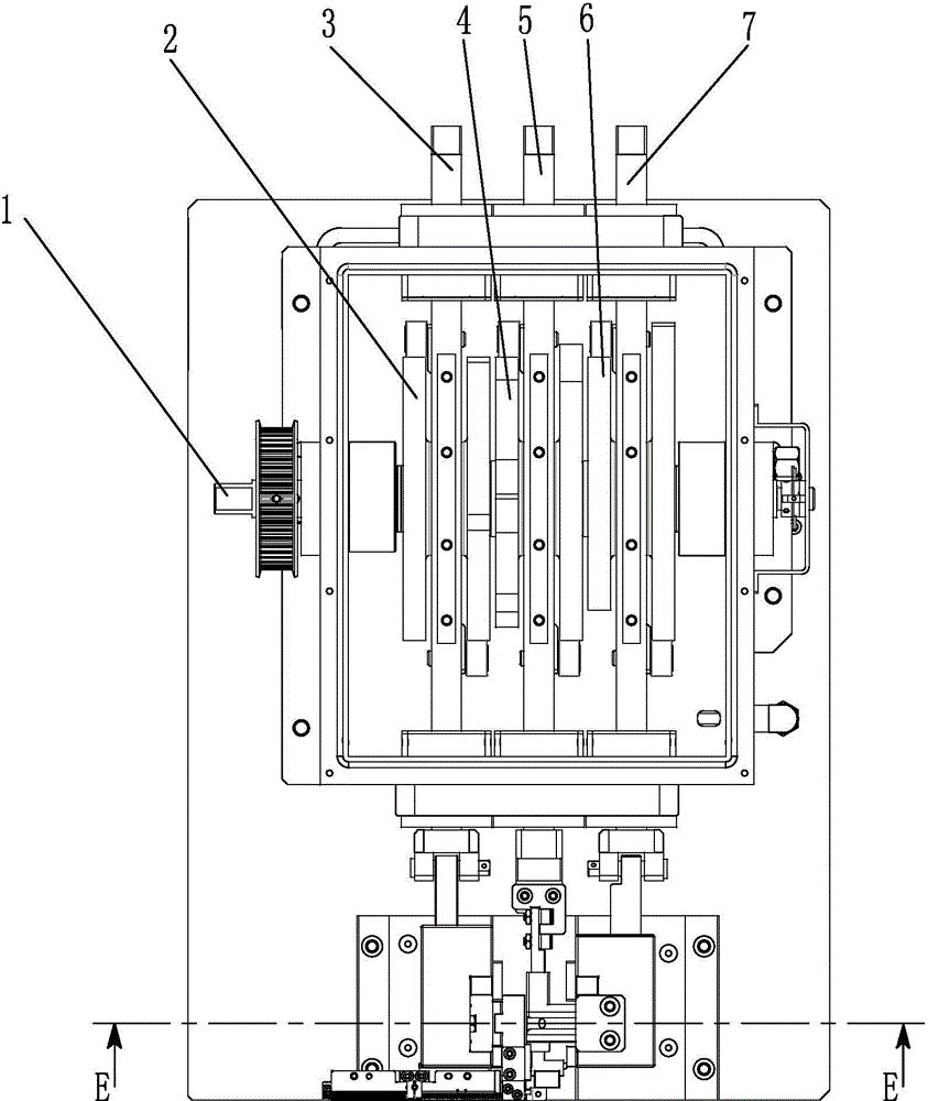
[0021] like Figure 1 to Figure 8 As shown, the terminal pin insertion device of the present invention includes a cam box 30, a cam connection shaft 1, a cutting cam 2, a pin insertion cam 4, a clamping cam 6, a cutting transmission shaft 3, a pin transmission shaft 5, a clip Material transmission shaft 7, cutting connection block 8, pin connection block 11, clamping connection block 16, upper knife track block 9, lower knife track block 10, first slider support 26, upper knife slider 20, lower Knife slider 21, upper cutting knife 22, lower cutting knife 23, upper chuck slider 12, lower chuck slider 13, upper chuck 24, lower chuck 25, upper chuck track block 18, lower chuck Head track block 19, upper chuck slider 14, lower chuck slider 15, second slider ...


PUM


Abstract

The invention provides a terminal pin plugging device comprising a cam box body, a cam connecting shaft, a cutting cam, a pin plugging cam, a material clamping cam, a cutting transmission shaft, a pin plugging transmission shaft, a material clamping transmission shaft, a cutting connecting block, a pin plugging connecting block, a material clamping connecting block, an upper knife track block, a lower knife track block, a first slide block supporting base, an upper knife slide block, a lower knife slide block, an upper cutting knife, a lower cutting knife, an upper clamping head slide rod, a lower clamping head slide rod, an upper clamping head, a lower clamping head, an upper clamping head track block, a lower clamping head track block, an upper clamping head slide block, a lower clamping head slide block and a second slide block supporting base. A cutting mechanism, a material clamping mechanism and a pin plugging mechanism are driven to actuate orderly by the cam connecting shaft so that motions of terminal material clamping, terminal cutting and terminal pin plugging can be completed by the terminal pin plugging device in an integrated way, and the terminal pin plugging device is high in processing precision, high in speed and high in production efficiency.

Description

technical field [0001] The invention relates to a processing equipment for terminal parts, in particular to a cam type terminal pin insertion device. Background technique [0002] In the field of terminal parts processing, the traditional method is generally to manually insert terminals into the workpiece. During manual processing, it is easy to cause terminal deformation, missing terminals, and irregular arrangement of inserted terminals, resulting in defective products. With the rapid growth of consumer electronics, automotive electronics, and communication terminal markets, connectors, as an indispensable part of electronic equipment, are also rapidly growing in demand. And because many products have to face smaller and lighter development, there are certain requirements for terminal spacing, appearance size, and height, which put forward higher requirements for the development and application of connectors towards miniaturization and high density. It is obvious that the...

Claims


Application Information

Patent Timeline
Patent Type & Authority Applications(China)
IPC IPC(8): H01R43/00H01R43/16H01R43/20
CPCH01R43/00H01R43/16H01R43/20
Inventor 陈雄斌
Owner SUZHOU HANCHUAN CO LTD AKA HARMONTRONICS
Why Eureka
Try Eureka