
Amplifier power supply filter circuit

A technology of filter circuit and discharge source, applied in the field of filter circuit, can solve the problems of large area of ​​printed circuit board, waste of circuit board space, and many filter circuit devices, etc., and achieve the effect of low cost, lower component cost, and lower production cost.

Active Publication Date: 2015-09-09
NANJING AOTO ELECTRONICS CO LTD
View PDF6 Cites 0 Cited by
  • Summary
  • Abstract
  • Description
  • Claims
  • Application Information

AI Technical Summary

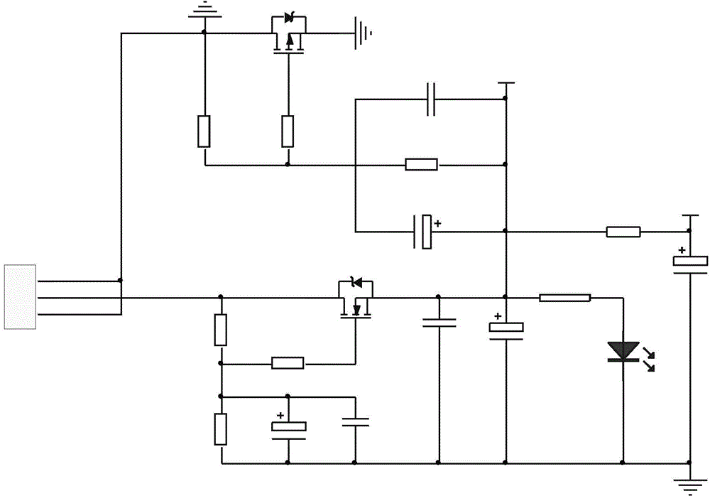
Problems solved by technology

[0003] Problems in the prior art: under the existing technical conditions, due to the large size of the transformer itself, the filter circuit realized by the transformer occupies a large area of ​​the printed circuit board, wasting the space of the circuit board; in addition, the price of the transformer itself is relatively high, And there are too many filter circuit components, resulting in high cost

Method used


Image

  • Amplifier power supply filter circuit

Examples


Embodiment Construction

[0010] The present invention will be described in further detail below in conjunction with the accompanying drawings and specific embodiments.

[0011] In the present invention, a MOS tube is used instead of a commonly used transformer to filter the power supply and the ground respectively, which can effectively isolate the power supply interference signal.

[0012] This embodiment provides a power amplifier power filter circuit, which uses two MOS tubes instead of transformers to filter the power supply and ground respectively, thereby realizing the function of isolating interference signals. The circuit schematic diagram is as follows figure 1 As shown: Among them, J1 is the power input terminal, which supports DC12V / 24V input. The input voltage Vin and ground DGND are filtered through N-MOS transistor QP0 and P-MOS transistor QP1 respectively, of which QP0 and QP1 are used as switches. After the circuit is connected to the power supply, after Vin is divided by RP0 and RP1, ...


PUM


Abstract

The present invention discloses an amplifier power supply filter circuit. Two MOS tubes are adopted to filter a power supply and the ground, an input voltage Vin and a ground DGND are filtered through an N-MOS tube QP0 and a P-MOS tube OP1, and the OP0 and OP1 serve as switches. After the circuit is connected to the power supply, voltage of the Vin is divided by RP0 and RP1, the Vin is then filtered by EP0 and CP0 so as to provide stable grid voltage for the QP0, the QP0 is at a conductive state, and the Vin is filtered by E1 and CP1 so as to output stable voltage VP and provide working voltage for an amplifier circuit. The voltage VP is pulled up by a resistor R2 and then is filtered by EP2 so as to output stable voltage VPA and provide working voltage for an amplifier chip. After voltage division of the VP through RP5 and RP3, a stable grid voltage is provided for the P-MOS tube QP1, the QP1 is at a conductive state, and the DGND outputs a stable ground signal GND after being filtered by EP2 and CP2.

Description

technical field [0001] The invention relates to a filter circuit, in particular to a power amplifier filter circuit. Background technique [0002] At present, on the power amplifier board, a transformer is usually used for filtering, isolating the electromagnetic interference signal affecting the power supply, and providing a stable and pure voltage to the power amplifier circuit. [0003] Problems in the prior art: under the existing technical conditions, due to the large size of the transformer itself, the filter circuit realized by the transformer occupies a large area of ​​the printed circuit board, wasting the space of the circuit board; in addition, the price of the transformer itself is relatively high, In addition, there are too many filter circuit components, resulting in high cost. Contents of the invention [0004] Aiming at the deficiencies in the prior art, the present invention aims to provide a filter circuit, which can isolate the electromagnetic interfere...

Claims


Application Information

Patent Timeline
Patent Type & Authority Applications(China)
IPC IPC(8): H02M1/44
Inventor 矫人全常彦青张岳琴陈文王勇
Owner NANJING AOTO ELECTRONICS CO LTD
Learn More