Oscillator circuit precisely controlled in duty ratio

A precise control and oscillator technology, applied in power oscillators, electrical components, generating electrical pulses, etc., can solve the problems of poor accuracy, occupied area, and complicated circuit duty cycle logic circuit design, so as to eliminate the need for logic generation circuits. , the effect of precise control of the duty cycle

Inactive Publication Date: 2015-09-09
SHENZHEN FM ELECTRONICS GRP CO LTD
View PDF5 Cites 9 Cited by
  • Summary
  • Abstract
  • Description
  • Claims
  • Application Information

AI Technical Summary

Problems solved by technology

[0005] However, the duty cycle logic circuit design of the above circuit is complicated, and the duty cycle is formed by using an RC circuit to generate a delay module, which occupies a large area, has high cost, and poor precision, and cannot realize a high-precision and high-frequency duty cycle adjustable oscillator circuit.

Method used


Image

  • Oscillator circuit precisely controlled in duty ratio
  • Oscillator circuit precisely controlled in duty ratio
  • Oscillator circuit precisely controlled in duty ratio

Examples


Embodiment Construction

[0019] Below, the present invention will be described in detail with reference to the accompanying drawings.

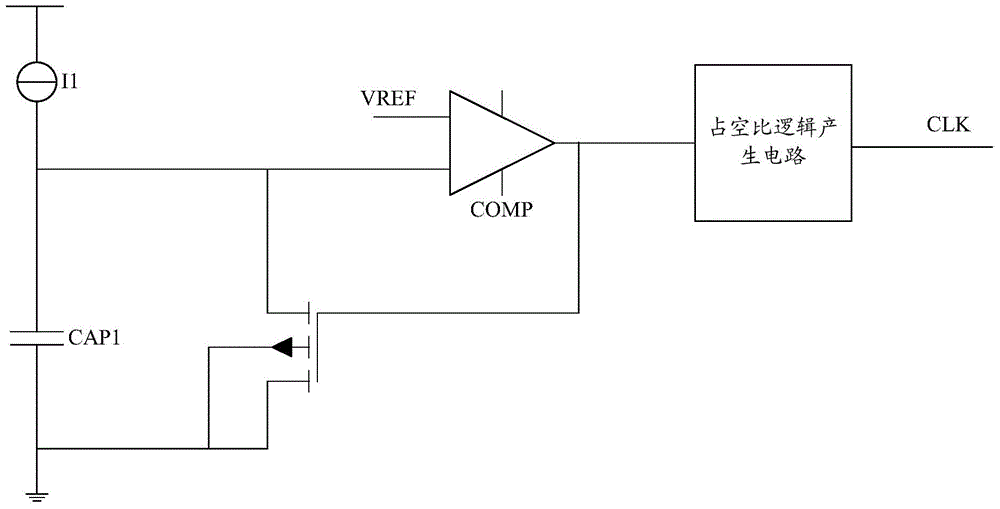
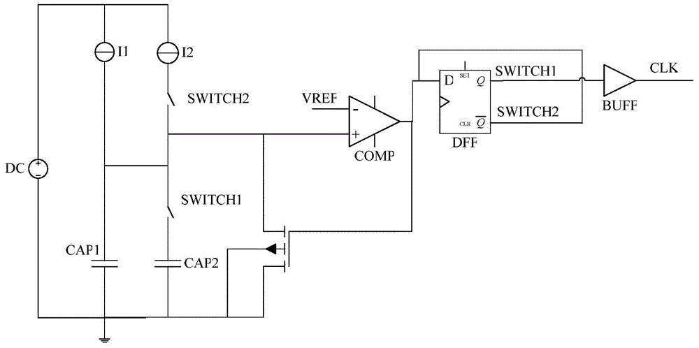
[0020] Such as figure 2 As shown, this embodiment provides an oscillator circuit capable of precisely controlling the duty cycle, wherein the positive terminal of the charging current I1 is connected to the positive terminal of the power supply, the negative terminal of the charging current I1 is connected to the positive terminal of the switch SWITCH1, and the charging current I2 The positive terminal of the charging current I2 is connected to the positive terminal of the power supply, the negative terminal of the charging current I2 is connected to the positive terminal of the switch SWITCH2, the negative terminal of the switch SWITCH2 is connected to the positive terminal of the switch SWITCH1, the positive terminal of the switch SWITCH1 is connected to the positive terminal of the charging capacitor CAP1, and the negative terminal of the switch SWITCH1 Connect th...


PUM


Abstract

The invention provides an oscillator circuit precisely controlled in duty ratio. By adopting charging current switching and charging capacitance switching mode, precise control over the pulse width of CLK high-low levels is realized, a duty ratio logic generating circuit is omitted, and the duty ratio can be precisely controlled. In a boost chip, the magnitude of a maximum duty ratio directly determines the maximum value of an output voltage, the oscillator circuit precisely controlled in duty ratio can effectively stabilize the amplitude of the output voltage, the area of the chip is simultaneously reduced, and the cost of the chip is reduced.

Description

technical field [0001] The invention relates to the technical field of oscillator circuits, in particular to an oscillator circuit capable of precisely controlling the duty cycle. Background technique [0002] Similar technologies currently on the market implement OSC (oscillator oscillator) by charging capacitors, such as figure 1 As shown, the oscillator circuit controlling the duty ratio in the prior art uses voltage comparison to generate a pulse signal, and then generates a signal with a fixed duty ratio through a duty ratio logic generating circuit. [0003] Among them, I1 is the charging current, one end of which is connected to the power supply voltage, the other end is connected to the positive end of the capacitor CAP1, the positive end of the comparator COMP is connected to the positive end of CAP1, the negative end is connected to the reference voltage VREF, and the output end is connected to the duty ratio logic generating circuit. At the input end, the output ...

Claims


Application Information

Patent Timeline
Patent Type & Authority Applications(China)
IPC IPC(8): H03K3/017H03B5/24
Inventor 秦鹏举杨敏林剑辉
Owner SHENZHEN FM ELECTRONICS GRP CO LTD
Why Eureka
Try Eureka