
Clock signal circuit for correcting high duty ratio

A technology of clock signal and duty cycle, which is applied to electrical components, generating electric pulses, transforming continuous pulse chains into pulse chain devices with required modes, etc., which can solve the problem of poor clock signal quality and poor clock duty Ratio

Pending Publication Date: 2021-03-16
CHENGDU ANALOG CIRCUIT TECH INC
View PDF3 Cites 0 Cited by
  • Summary
  • Abstract
  • Description
  • Claims
  • Application Information

AI Technical Summary

Problems solved by technology

In the prior art, the quality of the clock signal generated by the crystal oscillator or the RC oscillator is sometimes not very good, and there will be a poor clock duty cycle.

Method used


Image

  • Clock signal circuit for correcting high duty ratio

Examples


Embodiment Construction

[0026] It should be understood that the specific embodiments described here are only used to explain the present invention, not to limit the present invention.

[0027] The present invention will be further described below in conjunction with the accompanying drawings.

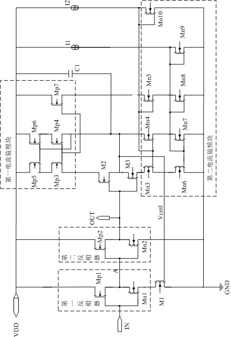
[0028] An embodiment of the present invention provides a circuit for correcting a clock signal with a high duty ratio, which is used for adjusting an input clock signal with a high duty ratio to output a clock signal with a duty ratio required by a subsequent circuit.

[0029] Such as figure 1 As shown, the clock signal circuit for correcting a high duty cycle according to the embodiment of the present invention includes a first inverter, a second inverter, a first current mirror module, a second current mirror module, and a first control field effect transistor M1, The second control field effect transistor M2 and the third control field effect transistor M3; the first inverter is respectively connected to t...


PUM


Abstract

The invention discloses a clock signal circuit for correcting a high duty ratio, and relates to the technical field of integrated circuits. The circuit comprises a first inverter, a second inverter, afirst current mirror module, a second current mirror module, a first control field effect transistor, a second control field effect transistor and a third control field effect transistor, the first phase inverter is connected to the signal input end and the second phase inverter, and the second phase inverter is connected to the signal output end; the first control field effect transistor is connected to the first inverter, the second control field effect transistor, the third control field effect transistor, the first current mirror module and the second current mirror module; the second control field effect transistor and the third control field effect transistor are connected to the signal output end; the first current mirror module is connected to the second control field effect transistor, and the second current mirror module is connected to the third control field effect transistor. According to the technical scheme, the duty ratio of the output waveform of the signal output endis accurately controlled by controlling the current of the mirror images of the first control field effect transistor and the second current mirror module.

Description

technical field [0001] The invention relates to the technical field of integrated circuits, in particular to a clock signal circuit for correcting a high duty cycle. Background technique [0002] In modern circuit systems, the clock signal is the most commonly used signal, which can be generated by a crystal oscillator or an RC oscillator. Different circuit modules have different requirements on the clock signal. For example, the analog-to-digital converter requires the edge jitter of the input clock signal to be particularly small, the real-time clock circuit (RTC) requires the frequency of the input clock signal to be very stable, and the mixer (Mixer) in some radio frequency circuits requires the frequency generated by the local oscillator. The clock signal has a duty cycle other than 50%, in order to increase the conversion gain, and the frequency doubling circuit requires the clock signal duty cycle to be 50%. However, in the prior art, sometimes the quality of the cl...

Claims


Application Information

Patent Timeline
IPC IPC(8): H03K3/017H03K5/156
CPCH03K3/017H03K5/156
Inventor 罗婷
Owner CHENGDU ANALOG CIRCUIT TECH INC
Learn More