
Acusector control circuit

A control circuit and electro-acupuncture technology, applied in electrotherapy, positioning for physiotherapy, physical therapy, etc., can solve the problems of being unable to provide unilateral waveform, unable to control unilateral waveform, limiting the application range of electroacupuncture, etc., to achieve extended use Effects of life, energy saving, and simple circuit structure

Inactive Publication Date: 2011-10-05
中脉健康产业集团有限公司
View PDF4 Cites 3 Cited by
  • Summary
  • Abstract
  • Description
  • Claims
  • Application Information

AI Technical Summary

Problems solved by technology

[0005] The purpose of the present invention is to address the various shortcomings caused by the use of transformer coils in current general electroacupuncture to generate AC signals, and the current electroacupuncture control circuit cannot provide unilateral waveforms, nor can it regulate unilateral waveforms, which limits Practical problems in the application range of electroacupuncture, providing a new electroacupuncture control circuit

Method used


Image

  • Acusector control circuit
  • Acusector control circuit

Examples


Embodiment Construction

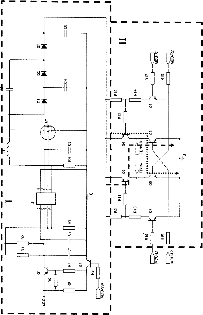
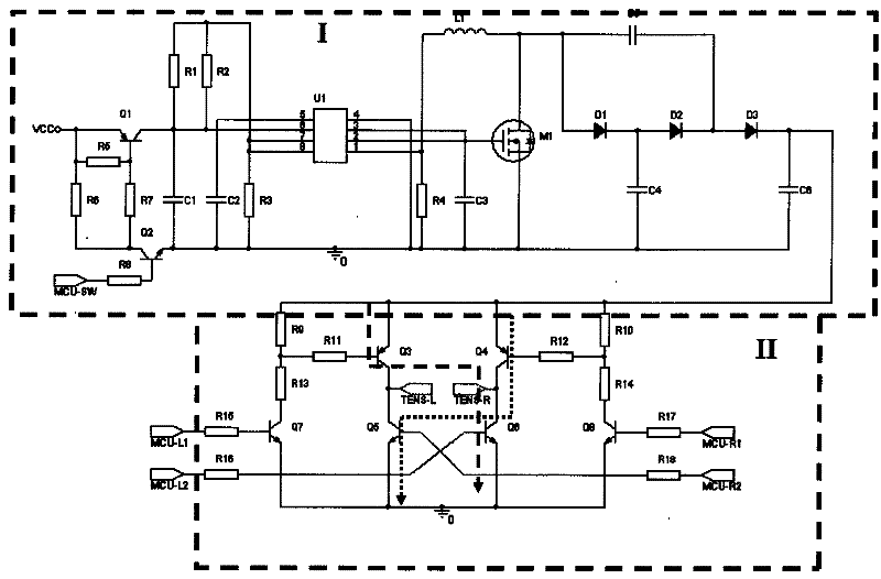
[0022] The accompanying drawings disclose the schematic circuit diagrams of the embodiments of the present invention without limitation, and the present invention will be further described below in conjunction with the accompanying drawings.

[0023] Depend on figure 1 It can be seen that the present invention includes a DC boost circuit I and an electroacupuncture bidirectional high-voltage excitation circuit II, wherein:

[0024] ——The DC boost circuit includes a working power supply, an electronic switch, a DC-DC boost circuit and a voltage doubler circuit. The working power supply is connected to the input end of the DC-DC boost circuit through an electronic switch. output of the voltage circuit.

[0025] ——The electroacupuncture bidirectional high-voltage excitation circuit includes a balanced bridge circuit composed of four high-power triodes, and a switch signal circuit that controls the on / off of the high-power triodes; a diagonal of the balanced bridge circuit is use...


PUM


Abstract

The invention relates to an acusector control circuit. The control circuit comprises a micro control unit (MCU) control chip, a direct current booster circuit and an acusector bilateral high voltage energizing circuit, wherein the direct current booster circuit comprises a working power supply, an electric switch, a direct current-direct current (DC-DC) booster circuit and a voltage doubling circuit; the working power supply is butted with the input end of the DC-DC booster circuit through the electric switch; the voltage doubling circuit is arranged at the output end of the DC-DC booster circuit; the acusector bilateral high voltage energizing circuit comprises a balanced bridge circuit consisting of four high-power triodes and a pair of electrodes; one corner of the balanced bridge circuit, serving as the load of the voltage doubling circuit, is connected with the output end of the balanced bridge circuit, and the other corner of the balanced bridge circuit is provided with the pair of electrodes serving as the bilateral direct current high voltage output ends of the acusector; and a control signal output by the MCU control chip respectively controls the electric switch and a switching signal circuit, and the MCU control chip provides synchronous control signals for the balanced bridge circuit.

Description

technical field [0001] The invention relates to an electric acupuncture control circuit, in particular to an electric acupuncture control circuit with low-frequency electric signal as output. Background technique [0002] Acupuncture is a discipline with a long history and a complete system in Chinese medicine. Doctors use human meridians as the core theory to regulate the flow of Qi and blood in the patient's body, so as to maintain the balance and stability of various tissues and organs in the body. In recent years, with the development of science and technology, according to the theory of human meridians in traditional Chinese medicine, electrical stimulation (Transcutaneous Electrical NerveStimulation, TENS) and laser acupuncture (Laser acupuncture) have been widely used in clinical practice, and have been proved by experiments. The effect is obvious. Compared with acupuncture needles used in traditional Chinese medicine, electroacupuncture is more convenient to use, s...

Claims


Application Information

Patent Timeline
Patent Type & Authority Applications(China)
IPC IPC(8): A61N1/08A61N1/20A61H39/00
Inventor 王尤山李富锋
Owner 中脉健康产业集团有限公司
Learn More