
Rotary-operation-type electronic component

A technology of rotary operation and electronic components, applied in the direction of contact operating parts, electrical components, circuits, etc., can solve the problems of torque reduction and misoperation of rotary operation, and achieve the effect of easy design

Active Publication Date: 2015-09-09
TOKYO COSMOS ELECTRIC CO LTD
View PDF7 Cites 3 Cited by
  • Summary
  • Abstract
  • Description
  • Claims
  • Application Information

AI Technical Summary

Problems solved by technology

However, if the operation knob is enlarged, a large operation torque will be applied to the operation shaft, so it is easy to apply unexpected force due to excessive rotation, or being surprised by unexpected force, sudden sound, light, etc. from the outside during operation. Misoperation due to desired rotation
Or, with the miniaturization of portable electronic equipment, the miniaturization of rotary operation type electronic components, as a result, the operating torque required for rotary operation will inevitably decrease, which will easily cause the same problem of misoperation.

Method used


Image

  • Rotary-operation-type electronic component
  • Rotary-operation-type electronic component
  • Rotary-operation-type electronic component

Examples


Embodiment

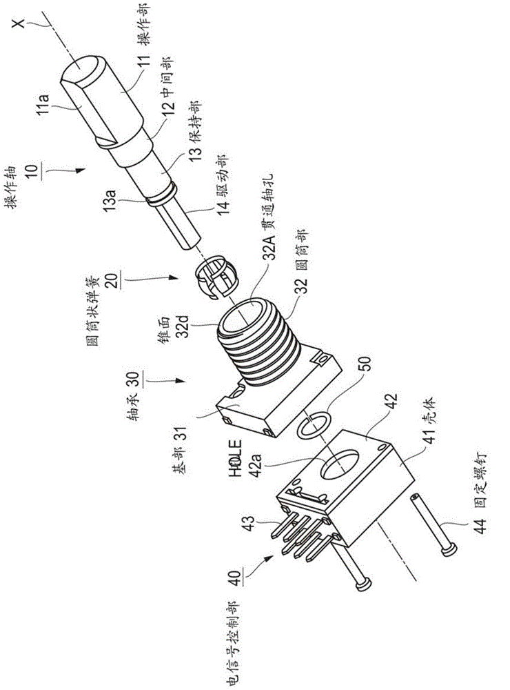
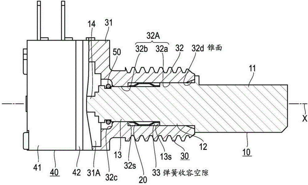
[0027] figure 2 It is a perspective view showing that each part of the rotary operation type electronic component of the present invention is arranged in an exploded manner in the central axis X direction, image 3 It shows a partial cross section of the central axis X direction of the assembled rotary operation type electronic component. The rotary operation type electronic component of the present invention is composed of: a cylindrical operating shaft 10 formed of metal; a cylindrical spring 20 formed of an elastic metal plate and breaking the ring in the axial direction; a bearing formed of metal or resin 30; an electric signal control unit 40; and an anti-drop ring 50 made of a metal material that separates the ring.

[0028] The operating shaft 10 has: a cylindrical operating portion 11 formed by cutting a desired length parallel to the central axis X to form a flat surface 11a; a cylindrical intermediate portion 12 extending coaxially from the operating portion 11 and...


PUM


Abstract

Provided is a rotary-operation-type electronic component having a simple design. The present invention includes: a column-shaped operation shaft; a bearing having a pass-through shaft hole; an electrical signal control unit attached to one end of the bearing, for controlling an electrical signal by rotary operation of the operation shaft; and a cylindrical spring, in which the barrel is cut in the center axial direction, accommodated inside a spring accommodation gap formed between the outer peripheral surface of the operation shaft and the inner peripheral surface of the pass-through shaft hole; the cylindrical spring having a plurality of spring plate parts extending in the center axial direction of the operation shaft, arranged mutually connected in the circumferential direction on the outer peripheral surface of the operation shaft; and the number of spring plate parts and the maximum distortion of the spring plate parts being independently adjustable using a structure in which the plurality of spring plate parts have a central region part in the length direction that projects in a curve toward the outer side in the radial direction of the cylindrical spring, the spring plate parts being elastically sandwiched between the outer peripheral surface of the operation shaft and the inner peripheral surface of the pass-through shaft hole, and the length in the center axial direction of the spring plate parts being extendably maintained by the pressing force of the outer peripheral surface and the inner peripheral surface.

Description

technical field [0001] The present invention relates to a rotary operation type electronic component which changes the resistance between terminals or switches the electrical connection between terminals by rotating an operation shaft, and is mainly used in portable electronic devices. Background technique [0002] For example, sometimes a rotary switch or a rotary variable resistor used in a portable electronic device (hereinafter, collectively referred to as rotary-operated electronic components) may be operated while wearing gloves, or when it is difficult to When operating in an environment where delicate operations are performed. In order to deal with such a situation, there is a demand for a portable electronic device that is easy to operate by increasing the size of the operation knob for rotating the rotary operation type electronic component. However, if the operation knob is enlarged, a large operation torque will be applied to the operation shaft, so it is easy t...

Claims


Application Information

Patent Timeline
IPC IPC(8): H01H19/20H01C10/00H01H3/10
CPCH01C10/14H01C10/46H01H19/585H01H19/20H01H3/10H01H3/08
Inventor 福永太郎
Owner TOKYO COSMOS ELECTRIC CO LTD
Learn More