
Shank fracture traction reduction frame

A traction reduction and lower leg technology, applied in fractures, medical science, surgery, etc., can solve the problems of inability to apply reduction, sterile disinfection, and inability to resist traction, etc., to reduce the rate of bone nonunion, and to facilitate direct traction reduction. The effect of fixing and saving operation time

Active Publication Date: 2015-09-16
侯力强
View PDF6 Cites 1 Cited by
  • Summary
  • Abstract
  • Description
  • Claims
  • Application Information

AI Technical Summary

Problems solved by technology

[0004] The purpose of the present invention is to provide a calf fracture traction reduction frame, which aims to solve the problems that the existing device cannot be sterilized, can not be used for reduction in surgery, or cannot resist traction during the traction process of the fracture site.

Method used


Image

  • Shank fracture traction reduction frame
  • Shank fracture traction reduction frame

Examples


Embodiment Construction

[0019] In order to make the object, technical solution and advantages of the present invention clearer, the present invention will be further described in detail below in conjunction with the accompanying drawings and embodiments. It should be understood that the specific embodiments described here are only used to explain the present invention, not to limit the present invention.

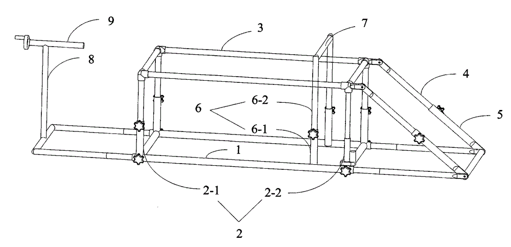
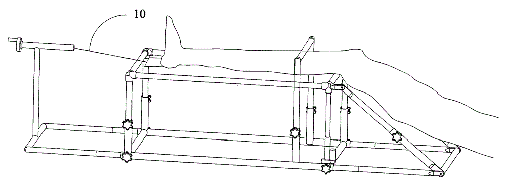
[0020] Such as figure 1 with 2 As shown, among them, figure 1 It is a structural schematic diagram of the calf fracture traction reduction frame of the present invention; figure 2 It is an effect diagram of the use state of the calf fracture traction reduction frame of the present invention.

[0021] A calf fracture traction reduction frame, comprising a base 1, a telescopic calf support frame 2 is provided in the middle of the base 1, and a calf support frame 3 with a square frame structure is provided at the top of the calf support frame 2; the calf support frame 3 is on the same side The tw...


PUM


Abstract

The invention provides a shank fracture traction reduction frame. The shank fracture traction reduction frame comprises a base, the central portion of the base is provided with a telescopic shank supporting frame, the top end of the shank supporting frame is provided with a shank support of a square frame structure, and the shank support is wrapped by leather; the two summits at the same side of the shank support are each hinged to a thigh solid support rod, the ends, which are away from the direction of the shank support, of the two thigh solid support rods are inserted into thigh hollow support rods, and the rod walls of the thigh hollow support rods are provided with threaded openings cooperating with screws for fastening the thigh solid support rods; the ends, which are away from the direction of the thigh solid support rods, of the two thigh hollow support rods are respectively hinged to the two summits at the same side of the base; the central portion of the base is also provided with a telescopic blocking supporting frame, and the top end of the blocking supporting frame is provided with a blocking rod; and the side, which is away from the direction of the thigh hollow support rods, of the base is provided with a telescopic traction support rod, and the top end of the traction support rod is provided with a crank screw rod. According to the invention, the shank fracture traction reduction frame is convenient to use, reduces wounds, saves operation time, increases the bone healing rate, reduces the pains of patients, and facilitates recovery of the patients.

Description

technical field [0001] The invention belongs to the field of medical devices, in particular to a traction reduction frame for calf fractures. Background technique [0002] The tibia and fibula of the lower leg are the most frequently fractured long tubular bones, accounting for about 10% of total body fractures, and traffic injuries are the most common. Because the anteromedial tibia is located under the skin, fractures are often serious, and most require surgical treatment. Traction is required both before and during the operation. The Brownian frame has no resistance before the operation, and the weight of the traction is more lost. Slow and continuous traction is required. The fracture end can move, and the patient has obvious pain. The fixed bracket also requires manual traction during the operation. It is often difficult to reset without resisting traction, and it is difficult to maintain even if it is reset. Especially for young people who are muscular, open reduction...

Claims


Application Information

Patent Timeline
IPC IPC(8): A61F5/042A61B17/56
Inventor 侯力强
Owner 侯力强
Learn More