Protruded spiral groove type swirler

A technology of helical groove and cyclone, which is applied in the direction of cyclone devices, devices whose axial direction of cyclone can be reversed, etc., can solve the problems of separation efficiency influence and unsatisfactory effect, so as to reduce overflow and run rough, and prevent Unreasonably flipped, widely used effects

Active Publication Date: 2015-09-16
QINGDAO INST OF BIOENERGY & BIOPROCESS TECH CHINESE ACADEMY OF SCI
View PDF8 Cites 4 Cited by
  • Summary
  • Abstract
  • Description
  • Claims
  • Application Information

AI Technical Summary

Problems solved by technology

As far as the overall structure of the cyclone is concerned, this improvement is only partial, and the effect is still not ideal in terms of greatly improving the separation efficiency of the cyclone
In addition, the problem that the separated particles of the cylinder bounce back into the central light medium flow area on the wall of the cylinder and the problem that the deposited particles are rolled up again at the bottom of the round table is still unsolved, and the phenomenon of overflow and roughness is serious. This defect has an impact on the separation efficiency. very big

Method used


Image

  • Protruded spiral groove type swirler
  • Protruded spiral groove type swirler

Examples


Embodiment 1

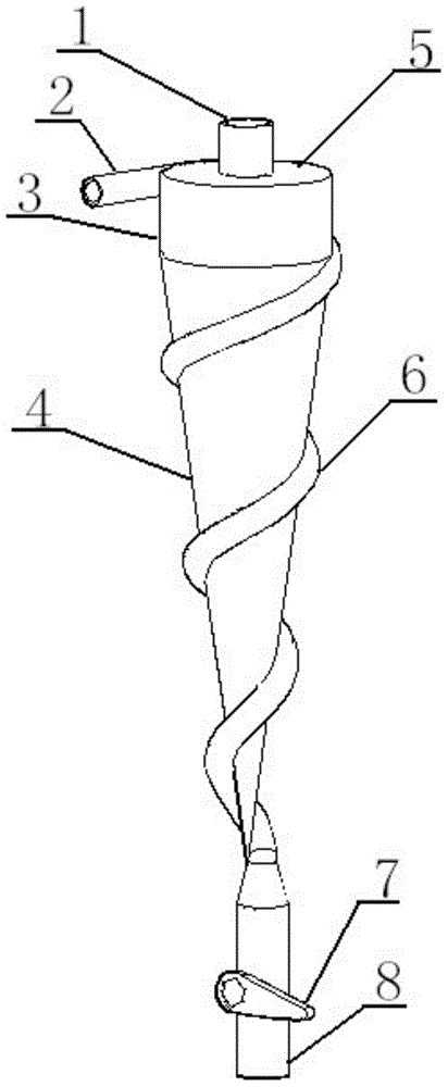
[0020] Such as figure 1 As shown, the cyclone of the present invention is an internal hollow structure, the top is a hollow cylindrical section 3, the bottom is a hollow conical section 4, the bottom surface of the cylindrical section 3 is connected to the bottom surface of the conical section 4, and the bottom of the conical section 4 is At the closed end, an overflow pipe 1 is connected to the center of the upper surface of the cylindrical section 3 , and the upper surface of the cylindrical section 3 can also be designed as a detachable top cover 5 , and the overflow pipe 1 is installed at the center of the top cover 5 . The axial centerlines of the overflow pipe 1, the cylindrical section 3 and the conical section 4 are collinear.

[0021] The feed pipe 2 communicates with the upper end of the cylindrical section 3, and is inclined downward relative to the cylindrical section 3 and is tangent to the cylindrical section 3. The downward inclination angle of the feed pipe 2 i...

Embodiment 2

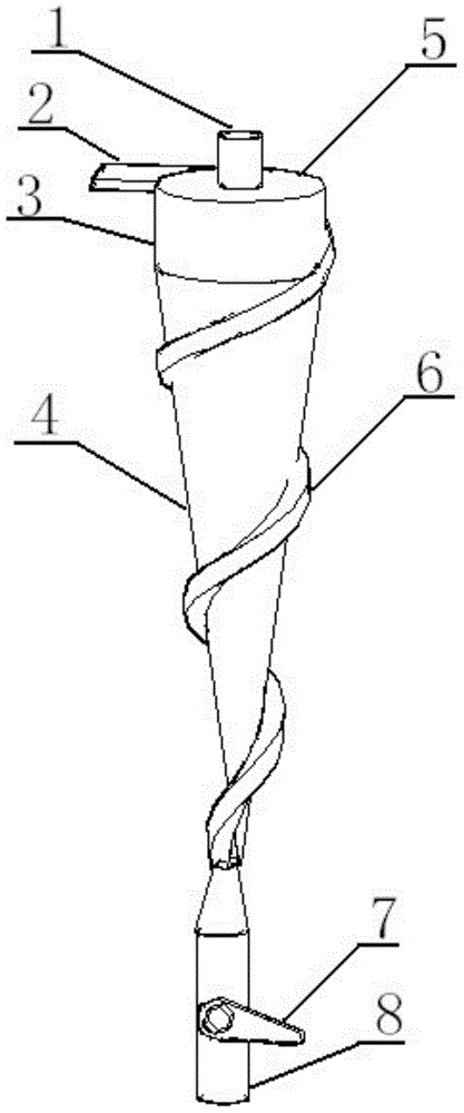
[0023] Such as figure 2 As shown, the difference between the present embodiment and the first embodiment is that the feeding pipe 2 of the present embodiment enters the cylindrical section 3 and forms an angle of 15-60° with the horizontal line and continues to extend downward along the wall of the cyclone and form a square shape. Protruding from the wall of the device is the spiral groove 6; that is, the cross-sectional shape of the spiral groove 6 in this embodiment is rectangular. Others are identical with embodiment one.

[0024] Working principle of the present invention is:

[0025] When the medium (material) to be separated enters the cyclone from the feed pipe 2, relying on the difference in the density of the light and heavy phases or the difference in the particle size between the coarse and fine particles, the centrifugal force and the drag force are different, forming an inner and outer two phases in the cyclone. Vortex, the heavy phase is thrown into the spiral...


PUM


Abstract

The invention relates to a protruded spiral groove type swirler. The swirler is of a hollow structure, wherein a hollow cylinder section is arranged at the upper part of the swirler, and a hollow cone section is arranged at the lower part of the swirler; a feeding pipe is communicated to the upper end of the cylinder section, downward inclines relative to the cylinder section and is tangent to the cylinder section, an overflow pipe is inserted into the cylinder section, and the bottom of the cone section is a closed end; a spiral groove is formed in the wall of the swirler in a manner that the wall of the swirler spirally and externally protrudes from top to bottom along the circumferential direction, the upper end of the spiral groove is communicated with the feeding pipe, and the lower end of the spiral groove is communicated with an underflow pipe; light and heavy mediums enter the swirler through the feeding pipe, the heavy mediums slide downward in the spiral groove and are discharged through the underflow pipe, and the light mediums are discharged through the overflow pipe, thereby realizing the separation of the light and heavy mediums. According to the protruded spiral groove type swirler, the separation of the light and heavy mediums can be led passingly when a swirling flow field is not changed, so that the grading efficiency is improved, the division diameter is decreased, and common overflow and thickening phenomena of the swirler are reduced.

Description

technical field [0001] The invention belongs to the field of material separation, in particular to the fields of gas-solid, liquid-solid, liquid-liquid, gas-liquid separation, and specifically relates to an outwardly protruding spiral groove type cyclone. Background technique [0002] The cyclone is a commonly used separation device at present. When working, a pump is used to drive the mixed phase into the cyclone from the feed pipe at the upper end under a certain pressure. Due to the difference in centrifugal force, two vortices, inner and outer, are formed in the cyclone. The heavy phase is thrown to the wall, slides down the wall, and is discharged from the bottom flow port, and the light phase flows out from the upper overflow port through the inner vortex. The cyclone has a simple structure, no moving parts, a small footprint, and a large production capacity, so it is widely used in the fields of gas-solid, liquid-solid, liquid-liquid, and gas-liquid separation. [00...

Claims


Application Information

Patent Timeline
Patent Type & Authority Applications(China)
IPC IPC(8): B04C5/081
Inventor 黄青山姚礼山
Owner QINGDAO INST OF BIOENERGY & BIOPROCESS TECH CHINESE ACADEMY OF SCI
Why Eureka
Try Eureka