Punching machine mechanical arm device

A technology of manipulator and punching machine, applied in the field of punching machine manipulator device, can solve the problems of affecting observation, affecting the loading and unloading and maintenance of punching die, and achieves the effect of convenient loading, unloading and maintenance.

Inactive Publication Date: 2015-09-16
SHENZHEN UNIV
View PDF8 Cites 25 Cited by
  • Summary
  • Abstract
  • Description
  • Claims
  • Application Information

AI Technical Summary

Problems solved by technology

This invention completes the feeding and receiving work of the punching machine through the self-contraction of the manipulator and the lateral sliding on the manipulator arm, which can improve the production efficiency and safety of the punching machine. However, since the vertical sliding cylinder is located in the middle of the main body of the manipulator, the whole The manipulator device can only be installed in front of the punch head of the punch press, which affects the observation during the operation, and also affects the loading and unloading and maintenance of the upper and lower molds on the punch press

Method used


Image

  • Punching machine mechanical arm device
  • Punching machine mechanical arm device
  • Punching machine mechanical arm device

Examples


Embodiment Construction

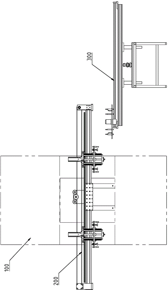
[0041] The punching machine manipulator device of the embodiment of the present invention is used to work with the punching machine, and is used for loading and unloading the disc-shaped workpiece. Its structure is as follows: Figure 1 to Figure 16 As shown, the punch manipulator device is installed on the workbench of the punch press 100, and a transfer table 300 is also equipped for unloading the workpiece and transferring it to the next process.

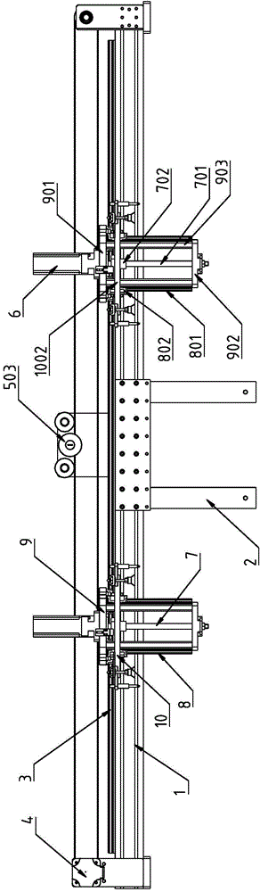
[0042] The punch manipulator device 200 includes a frame, two manipulators and a transverse drive mechanism.

[0043] The frame includes a beam 1 and a bracket 2 , the beam 1 is fixed on the bracket 2 , and the bracket 2 is fixed on the bed of the punch press 100 . The beam 1 is arranged behind the punch of the punch press 100 .

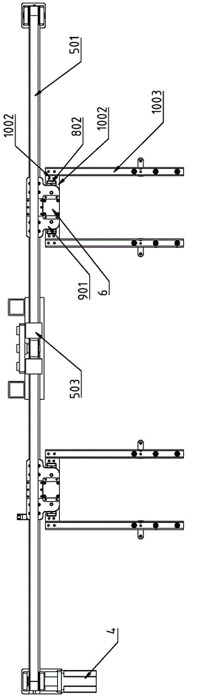
[0044] The transverse drive mechanism is installed on the beam 1. Manipulator comprises dolly 9, suction cup 10 and suction cup lifting mechanism.

[0045] The trolleys 9 of the two manipulators are ...


PUM


Abstract

The invention discloses a punching machine mechanical arm device. The punching machine mechanical arm device comprises a rack, two mechanical arms and a transverse driving mechanism, wherein the rack comprises a cross beam, the transverse driving mechanism is installed on the cross beam, each mechanical arm comprises a trolley, a sucking disk and a sucking disk lifting mechanism; the trolleys of the two mechanical arms are installed on the cross beam and arranged in a separating mode, the trolleys are driven by the transverse driving mechanism to conduct movement in the same direction; the travel distance of the movement the trolleys is the spacing distance between the two trolleys. The two mechanical arms of the punching machine mechanical arm device are provided with the two independent sucking disk lifting mechanisms, the cross beam of the mechanical arm device can be installed behind a punch of a punching machine, the front side of a punching machine die is provided with an air cylinder for shielding, the operation and the observation of operators can not be influenced, and the assembly and the disassembly and the maintenance of the punching machine die are also facilitated.

Description

[technical field] [0001] The invention relates to an accessory device of a punch press, in particular to a punch manipulator device. [Background technique] [0002] When the punch press is performing stamping operations, it needs to continuously feed materials into the mold and remove the stamped profiles in time. Most of the existing feeding and retrieving processes are completed manually or mechanically. When taking and feeding materials manually, the hands need to be inserted into the mold, which poses a great threat to personal safety. In addition, the manual operation is affected by work fatigue and seriously restricts the production efficiency of the product. [0003] The utility model with the patent number CN201320103330.4 discloses a single punch manipulator, which is used in the technical field of mechanical processing equipment, and includes a manipulator main body arranged on the punch machine body. A mechanical arm arranged on the frame body and a mechanical ar...

Claims


Application Information

Patent Timeline
Patent Type & Authority Applications(China)
IPC IPC(8): B21D43/18B21D45/06
CPCB21D43/18B21D45/06
Inventor 黄虹宾姜德卉黄丙耀黄雪
Owner SHENZHEN UNIV
Why Eureka
Try Eureka