Profile saw-cutting equipment

A profile and sawing technology, which is applied in metal sawing equipment, metal processing equipment, sawing machine devices, etc., can solve the problems of low work efficiency and long unloading time, and achieve the goal of improving work efficiency, saving time and improving work efficiency. Effect

Active Publication Date: 2015-09-16
山东辰禾智能装备有限公司
View PDF15 Cites 11 Cited by
  • Summary
  • Abstract
  • Description
  • Claims
  • Application Information

AI Technical Summary

Problems solved by technology

[0007] 3. The profile sawing equipment only has a feeding device, and there is no feeding device. As a result, when feeding, the next step of feeding can only be carried out after the previous batch of profiles has been sawed, resulting in low work efficiency.
[0011] The process of implementing the unloading device is that the manipulator first clamps the sawed profile, and when it reaches the cutting table, releases the profile, and then the manipulator backs up. The sawn profile is pushed to another workbench, and then the pushing device is backed up, and the manipulator performs the next feeding; in this unloading method, the material pushing device must wait until the manipulator is completely backed up before sawing. The good profiles are pushed to another workbench, and the manipulator has to wait until the pushing device is fully retracted before feeding the next time; therefore, this unloading method results in a relatively long unloading time and low work efficiency

Method used


Image

  • Profile saw-cutting equipment
  • Profile saw-cutting equipment
  • Profile saw-cutting equipment

Examples


Embodiment Construction

[0063] The present invention is described in detail below in conjunction with accompanying drawing:

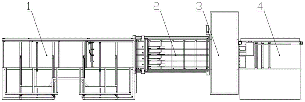
[0064] Such as Figure 1-Figure 7(2) As shown, a profile sawing equipment includes a feeding device 1, a feeding device 2, a sawing device 3 and an unloading device 4 arranged in sequence according to the feeding direction of the profile. The specific structure of each part is as follows:

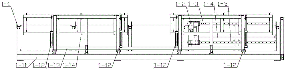
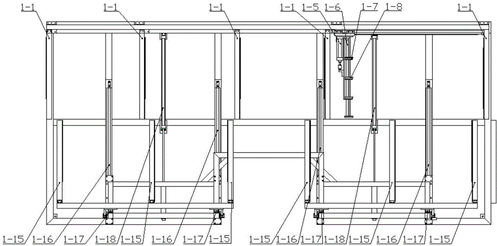
[0065] The specific structure of feeding device 1 is as follows:

[0066] Feeding device 1 includes profile fixed bracket 1-1; moving plate 1-2; linear guide rail 1-3; rodless cylinder 1-4; cylinder 1-5; guide shaft 1-6; Splint 1-8; Movable plate 1-9; Fixed plate 1-10; Base 1-11; Lifting cylinder 1-12; Mobile frame 1-13; Lifting frame 1-14; Guide rail 1-16; lifting frame guide rail 1-17; cylinder 1-18; the specific structure is as follows:

[0067] One side of the base 1-11 is provided with a profile fixing bracket 1-1, and the opposite side is provided with a profile moving bracket 1-15...


PUM


Abstract

The invention discloses profile saw-cutting equipment comprising a loading device, a feeding device, a saw-cutting device and an unloading device which are sequentially arranged according to a profile feeding direction. The feeding device comprises a rack, the loading device is mounted at the head of the rack, a manipulator fixing frame is mounted on the upper portion of the rack, multiple manipulators used for clamping a profile are mounted on the manipulator fixing frame, and the manipulator fixing frame slides back and forth along the rack to convey the profile to space below the saw-cutting device; the saw-cutting device comprises a saw head seat, a front saw head and a rear saw head which are in front-rear arrangement in the horizontal direction are mounted at the bottom of the saw head seat, central lines of the front saw head and the rear saw head form an angle of 45 degrees, the front saw head and the rear saw head are driven by respective cylinders to realize feeding or returning along a direction perpendicular to a direction in which the respective central lines are and are driven by respective motors to rotate respectively, and the unloading device comprises a discharging platform communicated with space below the saw-cutting device.

Description

technical field [0001] The invention discloses profile sawing equipment, which belongs to the field of numerically controlled door and window machine tools. Background technique [0002] With the popularization and development of plastic doors and windows, the production of doors and windows is developing in the direction of multi-style and large-scale. With the continuous growth of door and window enterprises, how to realize high-efficiency and mass production of a plastic door and window production line has become a direction for the development of door and window production, and has also become a direction pursued by door and window manufacturers. [0003] In the production of doors and windows, profile sawing equipment includes feeding device, sawing device and unloading device, but these devices have some defects, which will be analyzed in detail below. [0004] 1. When the feeding device is feeding, there are the following problems: [0005] 1. Most of the current fe...

Claims


Application Information

Patent Timeline
Patent Type & Authority Applications(China)
IPC IPC(8): B23D45/10B23D47/06B23D47/10B23Q7/04B23Q7/00
Inventor 赵延胜昃向博李国平
Owner 山东辰禾智能装备有限公司
Why Eureka
Try Eureka