
Novel automatic electric welding machine with auxiliary discharging mechanism

An auxiliary discharge and electric welding machine technology, applied in arc welding equipment, welding equipment, manufacturing tools, etc., can solve the problems of electromagnetic interference of the power grid, poor welding quality, low power utilization efficiency, etc., and achieve the effect of slowing down the performance index requirements.

Inactive Publication Date: 2015-09-16
HUZHOU YANHONG ELECTRONICS CO LTD
View PDF9 Cites 1 Cited by
  • Summary
  • Abstract
  • Description
  • Claims
  • Application Information

AI Technical Summary

Problems solved by technology

For some electric welding machines with poor design or working conditions, because this link cannot be guaranteed, it often leads to low power utilization efficiency, large electromagnetic interference to the power grid, poor solder joint appearance, and poor welding quality, etc. various adverse effects

Method used


Image

  • Novel automatic electric welding machine with auxiliary discharging mechanism

Examples


Embodiment 1

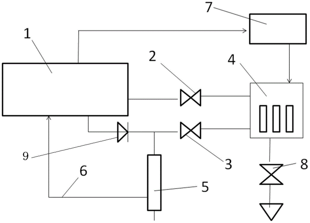
[0033] Preferred embodiment one: the welding machine host 1 with ordinary automatic control is applied, and the energy storage device 4 and the energy storage device controller 7 are configured to it, wherein the energy storage device 4 is a set of power capacitors with a switch matrix to control the power capacitors The energy storage device controller 7 adopts a single-chip microcomputer system to realize the connection form of the energy storage device. The energy storage device controller 7 can carry out RS485 serial communication with the overall controller of the welding machine host 1 and accept the control instructions of the whole machine. In addition to establishing a communication connection with the welding machine host 1, the energy storage device 4 is also connected to the welding machine host 1 and the welding torch 5 through a charging switch 2 and a discharging switch 3, and can be discharged to the ground through a ground discharge switch 8. The charge switch 2...

Embodiment 2

[0036] Preferred embodiment two: the welding machine host 1 with automatic control is adopted, the energy storage device 4 and its controller 7 are configured, and the charge and discharge switches are the same as in the first embodiment. The main machine 1 of the welding machine adopts an intermittent working mode of continuously welding three welding points, intermittently, and then continuously welding three welding points. The energy storage device 4 is configured into three groups through the energy storage device controller 7, and the charging switch 2 is turned on during the intermittent period of the welding machine to charge the three groups of energy storage elements. After that, each welding spot is welded by the energy storage device The controller 7 controls a certain group of energy storage components to perform discharge assistance. After the three solder joints are welded, the three groups of energy storage components are charged again in an intermittent stage.

...

Embodiment 3

[0038] Preferred embodiment three: the welding machine host 1 with automatic control is adopted, the energy storage device 4 and its controller 7 are configured, and the energy storage element is a solar battery pack. When the solar energy is sufficient, the solar battery is always charged and fully charged In the state, the solar cells are divided into at least two groups and alternately perform auxiliary discharge work.

[0039] The characteristic of this embodiment is the application of new energy devices and the corresponding omission of the charging switch 2, but the nature of the auxiliary welding machine has not fundamentally changed. This embodiment can be regarded as the basic idea of ​​the present invention. A simple modification after the production of new technologies and new devices can also achieve good results.


PUM


Abstract

The invention relates to a novel automatic electric welding machine with an auxiliary discharging mechanism. The novel automatic electric welding machine with the auxiliary discharging mechanism comprises a welding machine main machine, a welding gun, an energy storing device, an energy storing device controller and control switches, and the control switches comprise a charging switch, a welding gun discharging switch and a ground discharging switch. The welding machine main machine is internally provided with a welding machine inverter power supply which is electrically connected with the energy storing device through the charging switch and can conduct charging on the energy storing device in idle hours; the welding machine main machine is connected to the welding gun through a diode, the welding machine main machine, the diode and the welding gun are connected with one anther in series and the welding machine main machine, the diode, the welding gun and a welding part together form a main discharge circuit; the energy storing device is connected with the welding gun through the welding gun discharging switch to form an auxiliary discharge circuit. Due to the existence of the auxiliary discharge circuit, the automatic welding machine can be assisted in conducting transition from a state of open circuit and inoperation to a state of short circuit and workpiece welding, the control difficulty of an original welding machine whole machine controller in the short process is greatly reduced, and a better welding effect is achieved.

Description

【Technical Field】 [0001] The invention belongs to the technical field of high-end equipment and industrial robots, and specifically relates to a new type of automatic electric welding machine with an auxiliary discharge mechanism. 【Background technique】 [0002] The current welding technology has generally adopted electric energy as the energy source for welding heating, and the electric welding machine itself has realized automation and digital control. With the continuous improvement of technology, after the welding machine is equipped with sufficient external action structure and internal working condition control software, it has begun to possess a certain degree of intelligence, which is widely used in industrial product manufacturing lines or field projects as welding robots The form plays a huge role. [0003] However, the nature of the welding operation has not changed, and it still depends on the welding gun to discharge electrical energy to the welding workpiece. For el...

Claims


Application Information

Patent Timeline
IPC IPC(8): B23K9/10
CPCB23K9/1006
Inventor 严利人刘志弘任涛
Owner HUZHOU YANHONG ELECTRONICS CO LTD
Learn More