
Hydraulic automatic clamp for turning motor shell

A motor shell and automatic technology, which is applied in the direction of metal processing machinery parts, manufacturing tools, metal processing equipment, etc., can solve the problems of insufficient control of clamping force, poor dynamic balance performance of manual clamps, and affecting the processing accuracy of parts, etc. , to achieve the effect of improving processing quality, strong clamping rigidity, and improving processing accuracy

Active Publication Date: 2015-09-16
NINGBO HAITIAN PRECISION MASCH CO LTD
View PDF8 Cites 9 Cited by
  • Summary
  • Abstract
  • Description
  • Claims
  • Application Information

AI Technical Summary

Problems solved by technology

The use of traditional fixtures to clamp and fix the motor housing has certain shortcomings: First, the clamping positioning point is far away from the bearing chamber, and the clamping rigidity is poor. During the turning process, the parts will be slightly deformed, resulting in 0.005mm It is difficult to guarantee the cylindricity of the cylindricity, and there are often out-of-tolerance situations. Therefore, it is necessary to appropriately reduce the turning feed rate during turning to ensure the cylindricity requirements; Therefore, it is necessary to reduce the spindle speed during turning, but this will affect the processing efficiency; thirdly, the traditional clamping needs to be clamped manually, and the manual control of the clamping force is not stable enough, which will easily lead to the deformation of the part clamping and low clamping efficiency. ; Fourth, the dynamic balance performance of the manual fixture is poor, and the fixture is prone to vibration during rotation, which affects the machining accuracy of the part

Method used


Image

  • Hydraulic automatic clamp for turning motor shell
  • Hydraulic automatic clamp for turning motor shell
  • Hydraulic automatic clamp for turning motor shell

Examples


Embodiment Construction

[0023] The present invention will be described in further detail below in conjunction with the embodiments of the drawings.

[0024] As shown in the figure, the hydraulic automatic fixture for turning and processing the motor housing includes a hollow clamping body 1, a packing 2 is installed on one side of the clamping body 1, and a main shaft (not shown) is opened on the packing 2 Packing taper hole 21 with matching outer diameter. Packing 2 is equipped with a number of hexagon socket screws 22 for threaded connection to the spindle. Packing 2 and the spindle are fixedly connected by a number of hexagon socket screws 22, clamping the other side of concrete 1 A flange cover 3 is installed, the outer end of the flange cover 3 is provided with an error-preventing limit block 31, and the error-preventing limit block 31 is provided with a slot 32. The slot 32 is connected to the boss 61 on the motor housing 6. The shape is adapted, the flange cover 3 is provided with an indexable cl...


PUM


Abstract

The invention discloses a hydraulic automatic clamp for turning a motor shell. The hydraulic automatic clamp comprises a hollow clamp body. A packing is installed on one side of the clamp body and provided with a packing conical hole matched with the outer diameter of a main shaft. The other side of the clamp body is provided with a blind flange. The blind flange is provided with a rotatable clamping mechanism. The clamping mechanism is connected with a pull rod. One end of the pull rod penetrates out of the packing conical hole. The pull rod is driven by a hydraulic rotating oil cylinder and matched with a main shaft conical hole. Under the drive of the pull rod, the clamping mechanism can rotate and clamp and fix the motor shell. The motor shell is clamped and fixed in a hydraulic automatic clamping mode, clamping is convenient, the clamping efficiency is high, the clamping rigidity is high, the clamping force is stable and adjustable, clamping deformation can be greatly reduced, the motor shell machining precision is improved, the cylindricity of 0.005 mm of a bearing housing can be ensured, the motor shell machining quality is improved, the cost is reduced, and benefits are improved.

Description

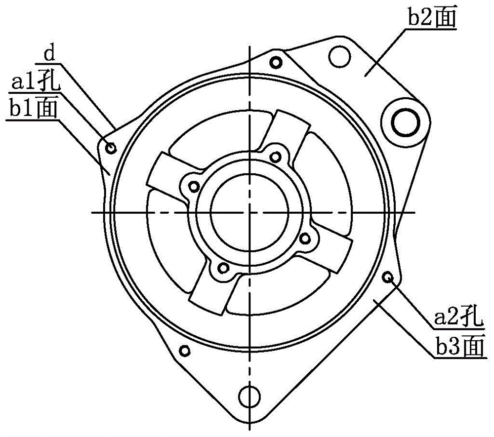
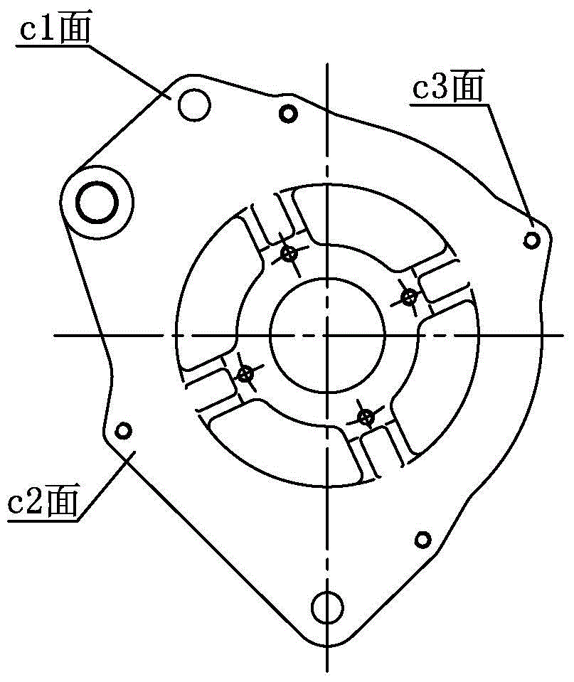
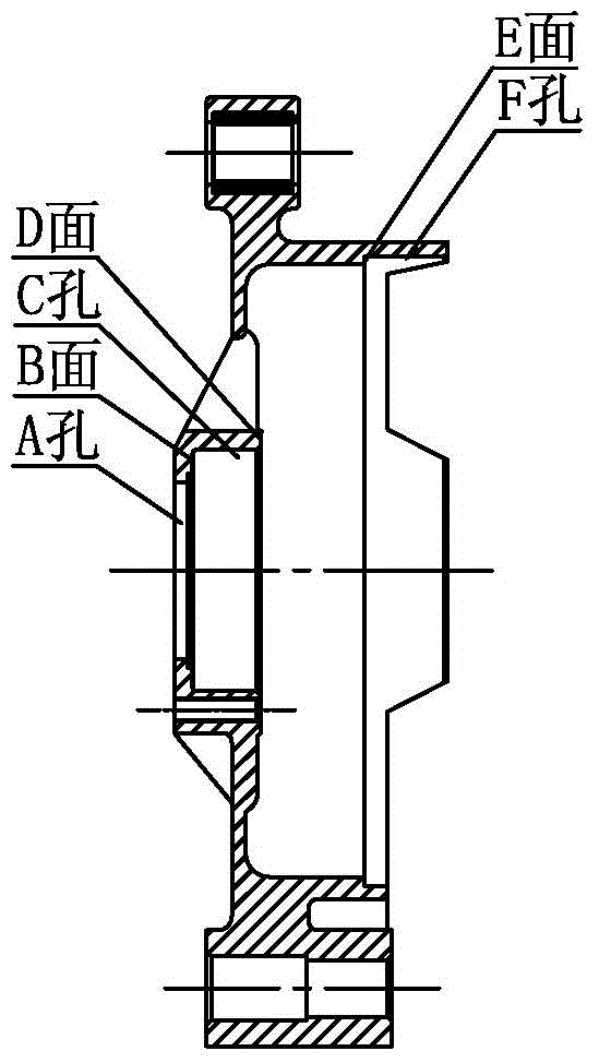
Technical field [0001] The invention relates to a fixture for numerical control machine tool processing, in particular to a hydraulic automatic fixture for turning and processing motor housings. Background technique [0002] The motor housing serves as the mounting part of the bearing and the rotor in the entire motor, and plays a key role in the stable rotation of the motor. The remarkable characteristic of the machining of the motor housing is that the machining content is mainly turning. Figure 1-3 It is a schematic diagram of the structure of a common motor housing, Figure 1-3 Among them, a1 hole and a2 hole are traditional clamping and positioning holes (a1 hole is opened on the boss d), b1, b2 and b3 are traditional clamping and pressing surfaces, c1, c2 and c3 are traditional Clamping positioning surface. Use traditional fixtures to fix the motor shell. When the motor shell is processed, press Figure 1-3 The corresponding clamping positioning holes, clamping pressing surf...

Claims


Application Information

Patent Timeline
IPC IPC(8): B23Q3/12
CPCB23B31/12
Inventor 葛运斌佟玉霞戴立昌李志明孙华权
Owner NINGBO HAITIAN PRECISION MASCH CO LTD
Learn More