Bottom mold guide rail lifting mechanism

A technology of bottom mold guide rail and lifting mechanism, which is applied in the direction of lifting frame, lifting device, etc., can solve the problems of bottom mold mechanism damage, achieve the effects of improving work efficiency, saving disassembly and assembly time, and saving installation space

Inactive Publication Date: 2015-09-16
JIANGSU NEWAMSTAR PACKAGING MACHINERY
3 Cites 4 Cited by

AI-Extracted Technical Summary

Problems solved by technology

Under normal circumstances, the bottom mold rises to the designated position before the mold is closed, and the protruding bayonet on the mold blocks the bottom mold; when an abnormal s...

Abstract

The invention discloses a bottom mold guide rail lifting mechanism. The bottom mold guide rail lifting mechanism is arranged on a bottle blowing machine and comprises a machine frame, a bottom mold mounting device, a driving air cylinder and a connecting member, wherein the bottom mold mounting device is arranged on the machine frame in a rising and falling manner, the driving air cylinder is arranged on the machine frame and is used for driving the bottom mold mounting device to rise and fall, and the connecting member is rotatably connected with the bottom mold mounting device; the driving air cylinder is horizontally arranged on the machine frame and comprises a cylinder barrel which is provided with an internal cavity, and a piston rod which is movably inserted in the internal cavity of the cylinder barrel, and one end of the piston rod is connected onto the connecting member. Through horizontally arranging the driving air cylinder, the air cylinder mounting space is effectively saved, and meanwhile, the air cylinder is not required to be dismounted while equipment is lifted, so that the time for dismounting is saved, and then the working efficiency is increased.

Application Domain

Technology Topic

Image

  • Bottom mold guide rail lifting mechanism
  • Bottom mold guide rail lifting mechanism

Examples

  • Experimental program(1)

Example Embodiment

[0017] The technical solutions of the present invention will be further described below in conjunction with the accompanying drawings and specific embodiments.
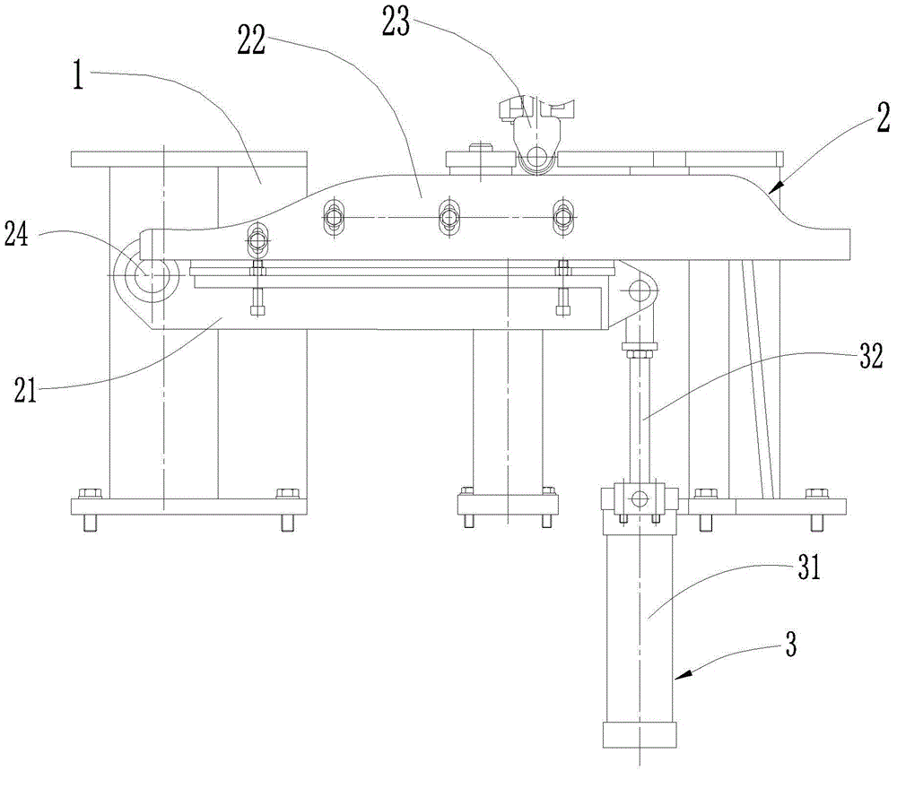
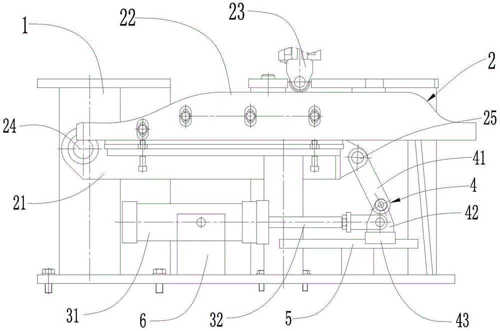
[0018] see figure 2 As shown, a bottom mold guide rail lifting mechanism is located on the blow molding machine, including a frame 1, a bottom mold installation device 2 that is lifted and lowered on the frame 1, and a bottom mold installation device 2 that is arranged on the frame 1 to drive the bottom mold. The driving cylinder 3 for the lifting of the installation device 2 and the connecting piece 4 that is rotatably connected with the bottom mold installation device 2 . The driving cylinder 3 is horizontally arranged on the frame 1, and includes a cylinder barrel 31 with an inner cavity, and a piston rod 32 movably inserted in the inner cavity of the cylinder barrel 31. connected. Here, by setting the driving cylinder 3 horizontally, the installation space of the cylinder is effectively saved.
[0019] In this embodiment, the bottom mold installation device 2 includes a bottom mold guide rail mounting seat 21 that is rotatably connected to the frame 1 at one end, a bottom mold guide rail 22 installed on the bottom mold guide rail mounting seat 21, The bottom mold support 23 on the mold guide rail 22, the connector 4 includes a connecting rod 41 that is rotatably connected to the bottom mold guide rail mounting seat 21, a slide block 43 that is horizontally slidably arranged on the frame 1, and is fixed on the frame 1. The hinge support 42 on the slide block 43 is fixedly connected to the hinge support 42 by the other end of the connecting rod 41 . Preferably, in this embodiment, one end of the piston rod 32 is also connected to the hinge support 42 . More preferably, the other end of the connecting rod 41 , one end of the piston rod 32 and the hinge support 42 are all fixedly connected at the same point.
[0020] In this embodiment, the elevating mechanism also includes a cylinder mounting seat 6 for installing the driving cylinder 3 on the frame 1, a slide rail 5 provided on the frame 1 for the slide block 43 to slide, and the slide block 43 is slidably arranged in the slide rail 5 along the length extension direction of the slide rail 5 . Preferably, the extending direction of the sliding rail 5 is parallel to the axial direction of the piston rod 32 . By setting the slide rail 5, the movement track of the slider 43 is effectively limited, thereby improving the stability and precision of the lifting mechanism of the present invention.
[0021] The working process of the bottom mold guide rail lifting mechanism is as follows: in the present embodiment, the bottom mold guide rail mounting seat 21 is hinged with the frame 1 through the first hinge shaft 24 on one end, and is hinged with the frame 1 through the second hinge shaft 25 on the other end. The connecting rod 41 is hinged. When the driving cylinder 3 drives the piston rod 32 to shrink, because the piston rod 32 is connected to the hinge support 42, the slide block 43 slides on the slide rail 5 along the shrinking direction of the piston rod 32, and then is fixedly connected to the hinge support 42. The connecting rod 41 drives the bottom mold guide rail mounting seat 21 to rotate downward around the first hinge shaft 24, so that the bottom mold guide rail 22 provided with the bottom mold support 23 installed on the bottom mold guide rail mounting seat 21 descends; when the driving cylinder 3 When driving the piston rod 32 to elongate, the slide block 43 slides on the slide rail 5 toward the elongation direction of the piston rod 32, and drives the bottom mold guide rail mounting seat 21 to rotate upwards around the first hinge shaft 24 through the connecting rod 41, thereby driving Bottom mold guide rail 22 rises.
[0022] The above-mentioned embodiments are only to illustrate the technical concept and characteristics of the present invention, and the purpose is to enable those skilled in the art to understand the content of the present invention and implement it accordingly, and not to limit the protection scope of the present invention. All equivalent changes or modifications made according to the spirit of the present invention shall fall within the protection scope of the present invention.

PUM

no PUM

Description & Claims & Application Information

We can also present the details of the Description, Claims and Application information to help users get a comprehensive understanding of the technical details of the patent, such as background art, summary of invention, brief description of drawings, description of embodiments, and other original content. On the other hand, users can also determine the specific scope of protection of the technology through the list of claims; as well as understand the changes in the life cycle of the technology with the presentation of the patent timeline. Login to view more.

Similar technology patents

Traditional Chinese medicine decoction device

ActiveCN105287216AReduces the risk of inconsistent decoction quality or drug mix-upsSave installation spacePharmaceutical product form changeDomestic articlesMedicinal herbsEngineering
Owner:永春县产品质量检验所福建省香产品质量检验中心国家燃香类产品质量监督检验中心福建

Emergency rescue vehicle

PendingCN107653920ARealize collaborative workSave installation spaceMechanical machines/dredgersEndless track vehiclesEngineeringEmergency rescue
Owner:JIANGSU XCMG CONSTR MASCH RES INST LTD

Classification and recommendation of technical efficacy words

  • Save disassembly time
  • Save installation space

Air-conditioner internal unit and air conditioner

PendingCN107525154ASave installation spaceCompact installation spaceCondensate preventionLighting and heating apparatusAirflowSpace requirements
Owner:GREE ELECTRIC APPLIANCES INC OF ZHUHAI
Why Eureka
Try Eureka