Vehicle accumulator monitoring method and system
A battery and battery voltage technology, applied in the field of automotive battery monitoring methods and systems, can solve problems such as excessive self-discharge, failure to charge, difficult battery, etc., to achieve the effect of avoiding insufficient electrolyte and ensuring performance
- Summary
- Abstract
- Description
- Claims
- Application Information
AI Technical Summary
Problems solved by technology
Method used
Image

Examples
Embodiment
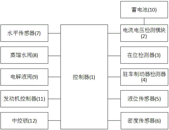
[0031] Embodiment: a kind of automobile storage battery monitoring system of the present embodiment, such as figure 1 As shown, it includes controller 1, current and voltage detection module 2, presence detector 3, parking brake detector 4, liquid level sensor 5, density sensor 6, level sensor 7, distilled water valve 8 and electrolyte valve 9. The controller is respectively connected with the presence detector, the current and voltage detection module, the parking brake detector, the liquid level sensor, the density sensor, the level sensor, the distilled water valve, the electrolyte valve, the engine controller 11 and the central lock 12. The current and voltage detection module is connected to the positive pole and the negative pole of the storage battery 10 . Both the distilled water valve and the electrolyte valve are electronically controlled valves. The liquid level sensor and density sensor are installed inside the battery, the parking brake detector is connected to t...
PUM
 Abstract
Description
Claims
Application Information
PatSnap Eureka turns technology decisions into work you can execute. Powered by our Innovation Knowledge Graph, it runs expert workflows across engineering, life sciences, materials and intellectual property. Get your review-ready output in minutes.


