
Double-side driven glass micro-nozzle processing device and processing method

A processing device, glass micro technology, applied in glass production, glass molding, glass manufacturing equipment, etc., can solve the problems of uncontrollable length of micro nozzle, different lengths at both ends, and deviation of breaking point from heat source, etc., to improve production The effect of efficiency and material utilization, good applicability and simple structure

Active Publication Date: 2015-09-16
XIAMEN UNIV OF TECH
View PDF9 Cites 11 Cited by
  • Summary
  • Abstract
  • Description
  • Claims
  • Application Information

AI Technical Summary

Problems solved by technology

[0005] In order to solve this problem, domestic researchers have done related research work. For example, the design idea of ​​Chinese Patent No. 201210123632.8 is to locally heat and stretch the glass microneedle to form a micronozzle with a relatively small inner diameter at the exit. By changing the pulling force and other operations To control the geometry of microneedles, although the patent proposes an automatic micronozzle maker that can simultaneously draw and forge, this invention only integrates the process of glass tube drawing and glass microneedle forging, and There is no integrated glass micro-nozzle grinding device, so the length of the prepared micro-nozzle cannot be controlled
[0006] In addition, the existing glass pipe drawing devices are fixed at one end and movable at the other end, but during the drawing process, the heat source is fixed, so the breaking point will deviate from the heat source, resulting in deformation of both ends of the glass pipe breaking point It is an asymmetric structure with different lengths at both ends

Method used


Image

  • Double-side driven glass micro-nozzle processing device and processing method
  • Double-side driven glass micro-nozzle processing device and processing method
  • Double-side driven glass micro-nozzle processing device and processing method

Examples


Embodiment Construction

[0040] The present invention will be described in further detail below in conjunction with the accompanying drawings and specific embodiments.

[0041] The invention discloses a double-end driven glass micro-nozzle processing method: by setting two symmetrically arranged drive mechanisms, the glass tube clamping devices at both ends of the glass tube are driven to move in opposite directions at the same time, so as to realize the drawing of the glass tube During the process, two micro-nozzles with symmetrical structure are formed at both ends of the break point.

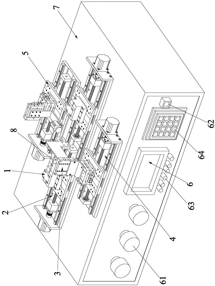
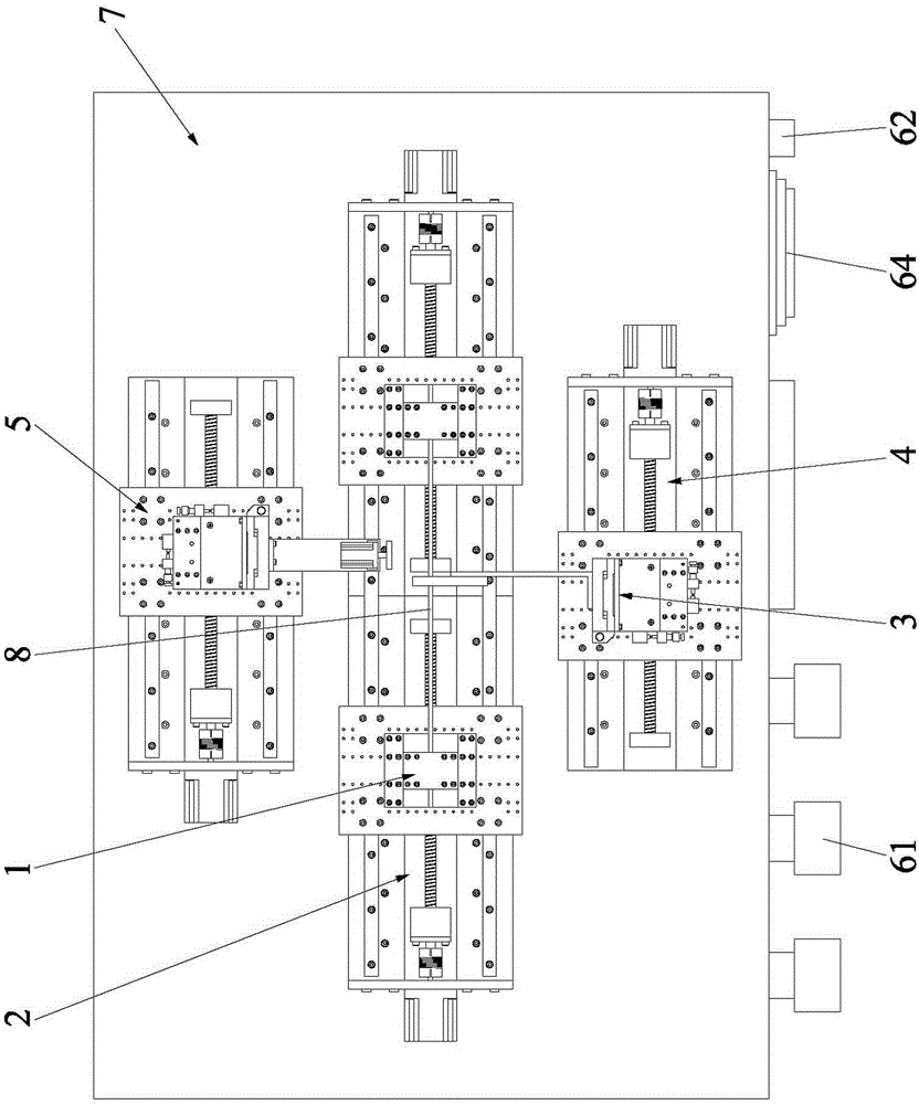
[0042] The invention also discloses a double-end driven glass micro-nozzle processing device, see Figure 1 to Figure 6 shown, is the preferred embodiment of the present invention. The processing device includes a glass tube clamping device 1 , a glass tube drawing motion device 2 , a heater device 3 , a forging motion device 4 , a grinding device 5 , a control device 6 and a base 7 . in:

[0043] The glass tube cla...


PUM


Abstract

The invention discloses a double-side driven glass micro-nozzle processing device and processing method. Glass tube clamping devices at two ends of a glass tube are driven to simultaneously move towards the opposite directions through the arrangement of two symmetrically arranged drive mechanisms, so that the drawing process of the glass tube is realized; two micro-nozzles with symmetrical structures are formed at two ends of a breaking point; a heater can be controlled to move to the corresponding positions at two ends of the breaking point of the glass tube to heat the nozzles, so as to finish the forging process of the two glass nozzles; and the glass nozzles are ground by a grinding device, so that the nozzles reach the required shapes. Two glass nozzles which are the same completely can be obtained in a double-end drawing manner, so that the utilization rate and the production efficiency of the material are improved; the operation is simple; and the problems of low production efficiency, low utilization rate and poor precision of the material in the past are well solved.

Description

technical field [0001] The invention belongs to the field of manufacturing micron (nano)-level glass nozzles, and particularly relates to a double-end driven glass micro-nozzle processing device and a processing method thereof. Background technique [0002] The micro-nozzle is one of the most critical components in the droplet ejection technology. The diameter of the droplet, the shape of the flow channel and the surface quality of the inner wall determine the diameter and ejection capability of the droplet. Micro-nozzle fabrication methods include photolithography, electroforming, micro-EDM (chemical) processing, glass tube drawing, etc. When the glass micro-nozzle is produced by the drawing method, glass tubes with different apertures and tapers are obtained by controlling the deformation length of the glass material and the heating time of each part. [0003] The glass micro-nozzle made by the drawing method has low fluid resistance and good compatibility with biological...

Claims


Application Information

Patent Timeline
IPC IPC(8): C03B23/045C03B23/047B24B19/22
CPCY02P40/57
Inventor 舒霞云谢丹李文望常雪峰王建廖龙兴谢伟
Owner XIAMEN UNIV OF TECH
Learn More