Self-relieving hydraulic cylinder and steel bar bending machine

A hydraulic cylinder and self-relieving technology, which is applied in the field of hydraulic cylinders, can solve problems that affect the service life of hydraulic cylinders, hydraulic cylinders do not have parts that prevent cylinder expansion, damage, etc., and achieve the effect of ensuring service life and reducing temperature rise

Active Publication Date: 2015-09-16
许昌思迪讴机械科技有限公司
View PDF8 Cites 6 Cited by
  • Summary
  • Abstract
  • Description
  • Claims
  • Application Information

AI Technical Summary

Problems solved by technology

[0002] The hydraulic cylinder includes a cylinder and a piston. The cylinder has a first inlet and outlet for hydraulic fluid and a second inlet and outlet. The piston is installed in the cylinder. The piston is connected to a connecting rod. In and out between the second outlet and the second outlet, it can drive the piston to run, and the piston drives the connecting rod to run, which can realize the hydraulic cylinder's work on the outside and meet the needs of some actions; in the prior art, the hydraulic cylinder does not have components to prevent cylinder expansion , when the piston is immovable, if you continue to fill the hydraulic fluid into it, the phenomenon of cylinder expansion will occur, so that the hydraulic fluid will heat up, affecting the service life of the hydraulic cylinder, or even damaging it.

Method used


Image

  • Self-relieving hydraulic cylinder and steel bar bending machine
  • Self-relieving hydraulic cylinder and steel bar bending machine
  • Self-relieving hydraulic cylinder and steel bar bending machine

Examples


Embodiment Construction

[0019] The present invention will be further described below in conjunction with the accompanying drawings.

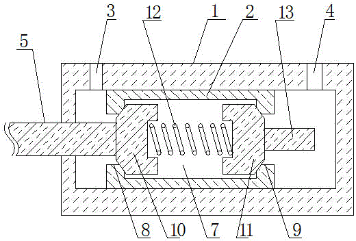
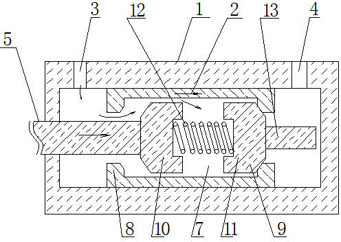
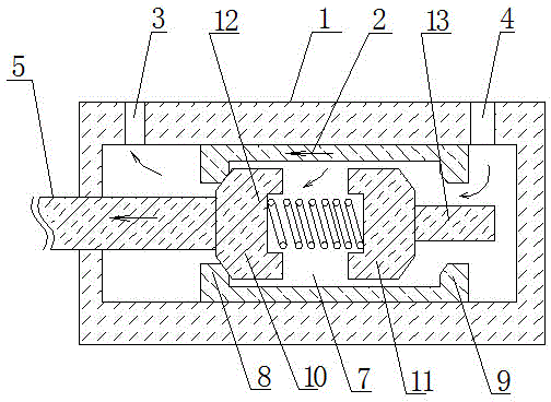
[0020] like figure 1 , 2 As shown in , 3, the self-releasing hydraulic cylinder includes a cylinder tube 1 and a piston 2, the cylinder tube has a first inlet and outlet 3 and a second inlet and outlet 4 for hydraulic fluid, and the piston 2 is installed in the cylinder tube 1 Inside, the piston 2 is connected with a connecting rod 5;

[0021] It is characterized in that: the inside of the piston has a hollow structure 7, the hollow structure is connected at both ends, the left end of the hollow structure is a left inner protruding edge 8, and the right end of the hollow structure has a right inner The protruding edge 9 has two conical blocks in the hollow structure, which are the left conical block 10 and the right conical block 11 respectively, and there is a spring 12 between the left conical block 10 and the right conical block 11. the groove and connect the lef...


PUM


Abstract

The invention relates to a hydraulic cylinder, in particular to a self-relieving hydraulic cylinder and a steel bar bending machine. The self-relieving hydraulic cylinder comprises a cylinder barrel and a piston, wherein the internal portion of the piston is provided with a hollow structure, the hollow structure is provided with a left inward convex edge and a right inward convex edge, the internal portion of the hollow structure is further provided with a left conical block and a right conical block, grooves for retaining a spring are formed between the left conical block and the right conical block, and the spring is connected with the left conical block and the right conical block; the back surface of the right conical block is fixedly connected with an ejector rod and the right end of the ejector rod exceeds the right side of the piston; a connecting rod is installed on the left conical block. The steel bar bending machine comprises a bending machine body, wherein the bending machine body is provided with a hydraulic cylinder which is said hydraulic cylinder. The self-relieving hydraulic cylinder has the advantages that the temperature of hydraulic fluid can be prevented from rising, the normal use is guaranteed and the phenomenon of cylinder expansion does not occur, and the operating speed can be further improved; the steel bar bending machine has the advantages that the temperature rise of the hydraulic cylinder is reduced and the service life is guaranteed.

Description

technical field [0001] The present invention relates to a hydraulic cylinder, and also relates to a steel bar bending machine equipped with the hydraulic cylinder. Background technique [0002] The hydraulic cylinder includes a cylinder barrel and a piston, the cylinder barrel has a first inlet and a second inlet and outlet for hydraulic fluid, the piston is installed in the cylinder barrel, the piston is connected with a connecting rod, and the hydraulic fluid is in the first inlet and outlet. It can drive the piston to run, and the piston drives the connecting rod to run, which can realize the external work of the hydraulic cylinder and meet the needs of some actions; in the prior art, the hydraulic cylinder has no parts to prevent the cylinder from expanding. , Continue to fill the hydraulic fluid into the cylinder when the piston is immovable, and the cylinder expansion phenomenon will occur, so that the hydraulic fluid will heat up, affecting the service life of the hyd...

Claims


Application Information

Patent Timeline
Patent Type & Authority Applications(China)
IPC IPC(8): F15B15/14
CPCB21F1/00F15B15/1414F15B15/1447
Inventor 马光辉
Owner 许昌思迪讴机械科技有限公司
Why Eureka
Try Eureka