Method for driving and controlling an electric motor

A drive control and motor technology, applied in motor control, control system, single motor speed/torque control, etc., can solve the problems of increased cost of temperature sensor components, unstable thermal conductivity, detection error, etc.

Inactive Publication Date: 2011-12-28
SHINANO KENSHI
View PDF6 Cites 3 Cited by
  • Summary
  • Abstract
  • Description
  • Claims
  • Application Information

AI Technical Summary

Problems solved by technology

Because the temperature of the coil is detected based on the thermal conductivity of the coil, not based on the temperature sensor provided to the motor casing, it is easy to cause detection errors due to unstable thermal conductivity
In addition, the temperature of the phase coil is estimated based on the temperature detected by the temperature sensor and the calculation process, so complex control must be required to perform this calculation process, and the component cost of the temperature sensor must increase

Method used


Image

  • Method for driving and controlling an electric motor
  • Method for driving and controlling an electric motor
  • Method for driving and controlling an electric motor

Examples


Embodiment Construction

[0029] Preferred embodiments of the present invention will now be described in detail with reference to the accompanying drawings. In the following embodiments, as an example of a motor, an in-vehicle three-phase DC brushless motor will be explained.

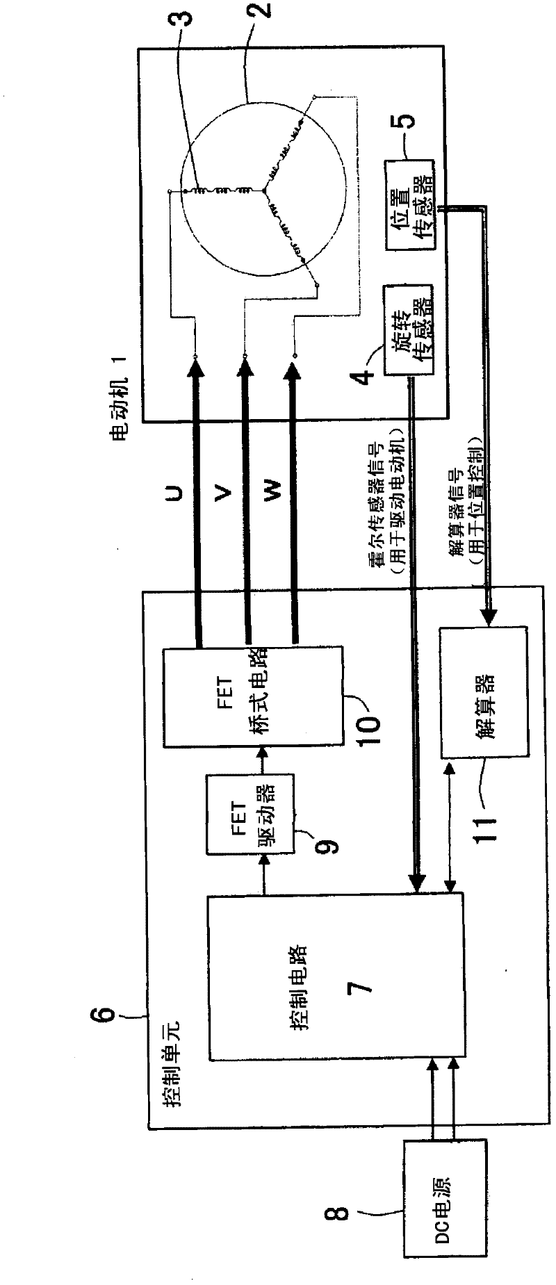
[0030] First, refer to figure 1 To explain the control system of the electric motor.

[0031] Electric motor 1 generates electrical energy to help press the clutch pedal. The electric motor 1 rotates in the normal direction or the reverse direction according to the pressing action or the returning action of the clutch pedal. Through the ball bearing screws of the auxiliary mechanism, the rotational movement of the electric motor 1 is converted into a linear movement, so that the clutch plates can be connected and disconnected. If the motor 1 is driven while the clutch pedal is pressed (in a load-holding stop state), there is a possibility that the maximum current passes through the motor coils 3 of a specific phase and these ...


PUM


Abstract

A method of the invention is capable of equalizing time lengths of stopping a motor at load-holding stop positions of respective phases so as to average amounts of heat generation of phase coils. The method for drive-controlling electric machinery, in which a multiphase motor is used as a driving source of an assist mechanism, is performed by a control unit including a driving circuit for driving the multiphase motor. The method is characterized in that the control unit controls to stop a rotor at a load-holding stop position, at which rotation of the rotor is stopped in a state where a motor coil is energized and the rotor is in a load-holding state, and that the load-holding stop position is angularly shifted an electric angle of 180 / n (n is number of phases and an integer two or more) degrees, in a prescribed rotational direction, with respect to a previous load-holding stop position of the rotor.

Description

technical field [0001] The invention relates to a method for driving and controlling an electric motor. Background technique [0002] An electric motor includes a rotor and a stator. The stator has a stator core, wherein the motor coils are wound on teeth with insulators. [0003] For example, in vehicles, electric motors are used to activate clutches, accelerators, and the like. Depending on the load, the rotational motion of the motor is converted into linear motion in order to transmit the linear motion. [0004] For example, clutch mechanisms have been developed in which an electric motor is driven according to the amount of depression of the clutch pedal to activate an auxiliary member to connect or disconnect the clutch plates; brake mechanisms in which the electric motor is driven according to the amount of depression of the brake pedal In order to activate an auxiliary component so as to apply the hydraulic pressure of the brake fluid to the master cylinder; and s...

Claims


Application Information

Patent Timeline
IPC IPC(8): H02P6/24H02P6/16H02P3/06H02P6/06H02P6/08
CPCH02P23/03H02P29/0044H02P29/60
Inventor 丸山将见
Owner SHINANO KENSHI
Why Eureka
Try Eureka