Electric driver and air vehicle and ship applying same

An electric drive, aircraft technology, applied in the direction of electric power device, electromechanical device, power device, etc., can solve the problem of partial cancellation of output torque, and achieve the effect of more power, heat dissipation, and efficiency improvement

Active Publication Date: 2016-02-17
ZHUHAI PANSHI ELECTRONICS TECH CO LTD
View PDF6 Cites 4 Cited by
  • Summary
  • Abstract
  • Description
  • Claims
  • Application Information

AI Technical Summary

Problems solved by technology

[0007] When more than two rotors are used for power output, most of the existing dual-rotor motors cannot realize the synchronization of the rotor power output well, and it is easy to cause the output torque of the two rotors to partially cancel each other

Method used


Image

  • Electric driver and air vehicle and ship applying same
  • Electric driver and air vehicle and ship applying same
  • Electric driver and air vehicle and ship applying same

Examples


Embodiment 1

[0052] Embodiment 1 (electric drive device)

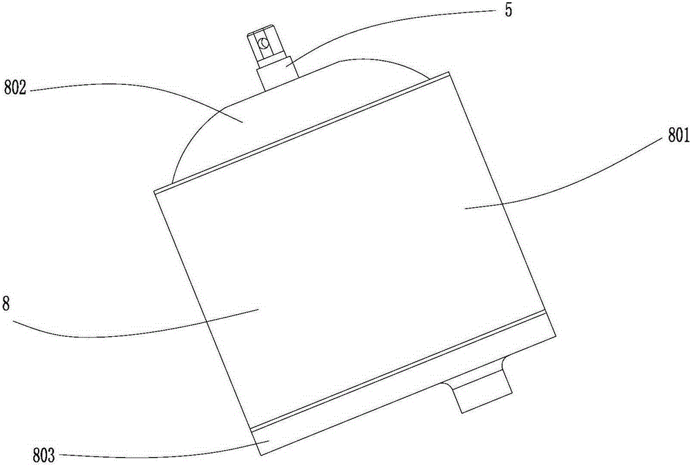
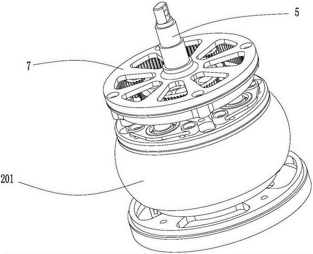
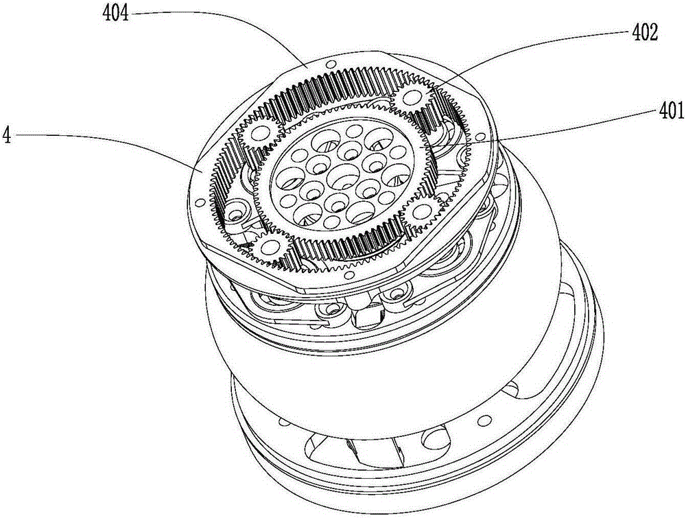
[0053] Such as Figure 1-Figure 8 As shown, the electric drive device of this embodiment includes: a first rotor system (inner rotor system 1), a second rotor system (outer rotor system 2), a separator 3, a synchronous output system 4, a motor output shaft 5, a first Connecting seat 6, second connecting seat 7, casing 8, braking system 9.

[0054] Such as Figure 7 As shown, the inner rotor system 1 includes an inner rotor 101 and an inner stator 102 arranged coaxially; the inner rotor 101 includes an inner shaft 105 and an inner magnet, and the inner shaft 105 is fixedly installed in a mounting hole on the base 803 through a bearing, and the inner magnet is fixed It is arranged outside the inner rotating shaft 105; the inner stator 102 is arranged outside the inner magnet; the partition 3 is arranged outside the inner stator 102, and the bottom of the partition 3 is screwed to the base 803.

[0055] Such as Figure 7 As shown,...

Embodiment 2

[0063] Embodiment 2 (electric drive device)

[0064] The difference between this embodiment and embodiment 1 is: as Figure 9 As shown, the first rotor 101 is located outside the first stator 102; the first rotor 101 drives the ring gear 404 to rotate; the second rotor 201 drives the planetary gear 402 to rotate around the sun gear 401 through the planet carrier 403; the motor output shaft 5 is connected to the sun gear Wheel 401 is fixedly connected.

Embodiment 3

[0065] Embodiment 3 (electric drive device)

[0066] Such as Figure 10 As shown, in this embodiment, the first rotor 101 drives the ring gear 404 to rotate; the second rotor 201 drives the planetary gear 402 to rotate around the sun gear 401 through the planet carrier 403 ; the motor output shaft 5 is fixedly connected to the sun gear 401 . The difference between this embodiment and Embodiment 2 is that: the first rotor 101 is located inside the first stator 102 .


PUM


Abstract

The invention provides an electric driver for an air vehicle and a ship. The electric driver comprises a motor output shaft; the electric driver further comprises a first rotor system, a second rotor system and a synchronous output system; the first rotor system comprises a first rotor and a first stator which are coaxially arranged; the second rotor system comprises a second rotor and a second stator which are coaxially arranged, and the first rotor and the second rotor are coaxially arranged; the synchronous output system comprises a sun gear, planet gears, planet carriers and a gear ring; the planet gears surround the sun gear and are meshed with the sun gear; the gear ring is arranged outside the planet gears in a sleeving mode and meshed with the planet gears; the planet gears are supported on the planet carriers; the sun gear, the gear ring and the planet gears have a two-input one-output relation, that is to say, any two of the sun gear, the gear ring and the planet gears are driven by the first rotor and the second rotor to rotate respectively, and the rest one is fixedly connected with the motor output shaft. According to the electric driver, by arranging the synchronous output system, rotating of the first rotor and rotating of the second rotor are synchronously output to the motor output shaft, mutual counteracting of output torque of the first rotor and the second rotor is avoided, the motor efficiency is significantly improved, and not only is the power higher, but also energy is effectively saved. The invention further provides the air vehicle and the ship applying the electric driver.

Description

technical field [0001] The invention relates to an electric drive device and an aircraft and a ship using the same. Background technique [0002] The dual-rotor motor has two mechanical shafts, which can realize the independent transmission of energy of the two mechanical shafts, and has good application prospects in fields such as hybrid electric vehicles and continuously variable transmissions. [0003] Chinese patent application 200610015892.8 discloses a double-stator double-rotor motor. On the other side of the bearing, piezoelectric ceramic sheets, stator elastic bodies, and rotors are symmetrically arranged, and are connected to the shaft by springs and nuts. Stainless steel is processed into The R-shaped transition shape stator is elastic body, the piezoelectric ceramic sheet is pasted on the back to make the stator, the two stators and the bottom plate are connected together by bolts, the friction material is processed into the rotor, and the stator is connected by ...

Claims


Application Information

Patent Timeline
Patent Type & Authority Applications(China)
IPC IPC(8): H02K7/116H02K16/00H02K7/102F16H1/32B64D27/24B63H21/17B60K1/00
CPCB60K1/00B63H21/17B64D27/24F16H1/32F16H2001/327H02K7/102H02K7/116H02K16/00Y02T50/60
Inventor 何春旺
Owner ZHUHAI PANSHI ELECTRONICS TECH CO LTD
Why Eureka
Try Eureka