

Vehicle brake apparatus
A technology for vehicle braking and wheel braking, applied in the directions of brakes, vehicle components, braking components, etc., can solve the problems of not interfering with suspension components, reducing the degree of freedom of arranging electric actuators, and complicated connection of electric actuators. , to achieve the effect of increasing the degree of freedom, improving the degree of freedom, and enhancing the connection performance
- Summary
- Abstract
- Description
- Claims
- Application Information
AI Technical Summary
Problems solved by technology
Method used
Image

Examples
no. 1 example
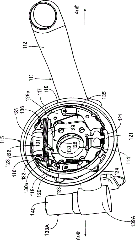
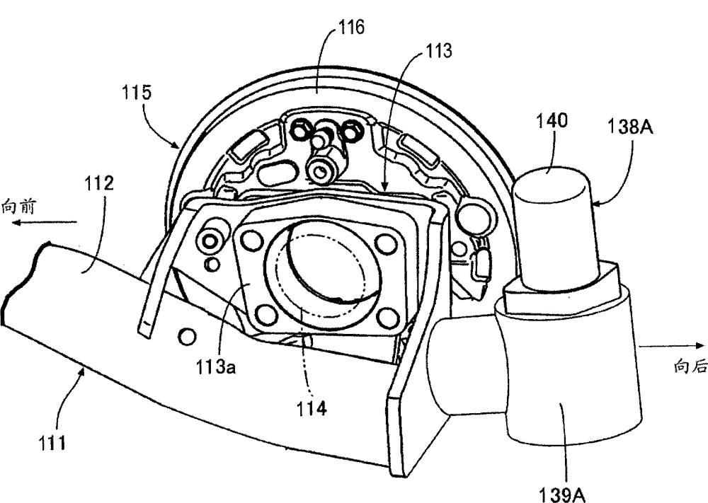
[0075] Refer below Figures 1 to 3 The first embodiment will be described. A steering knuckle 113 having a frame portion 113a is fixed to the rear end of a trailing arm 112 extending in the front-rear direction of the four-wheeled vehicle, and the trailing arm 112 constitutes a part of a suspension 111 by which the right rear wheel is supported in a suspended manner. on the body of a four-wheeled vehicle. The shaft 114 of the right rear wheel placed on the laterally outer side of the frame portion 113a is rotatably supported on the frame portion 113a.
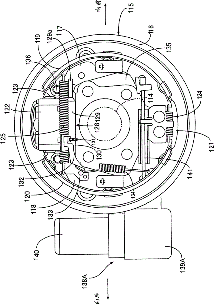
[0076] A brake shoe 116 of a drum brake 115 mounted on the right rear wheel is fixed to the frame portion 113a. The anchor block 121 is fixedly arranged on the lower part of the brake base plate 116, and the anchor block 121 constitutes a fulcrum on which a group of front main brake pads 117 and rear secondary brake pads 118 expand or contract. Friction pads 119, 120 configured to rotate with the right rear wheel are attache...
no. 2 example
[0098] Refer below Figure 4 and 5 A second embodiment will be described. The same reference numerals denote the same parts as those of the first embodiment, the same parts are only shown, and their detailed description is omitted here.
[0099] First, in Figure 4 Among them, the electric actuator 138B is configured to be activated to operate when the four-wheeled vehicle is parked, the electric actuator being connected to the brake shoe 116 of the drum brake 115 mounted on the left rear wheel of the vehicle. When the drum brakes 115 are attached to the vehicle, the electric actuator 138B is positioned further rearward than the axle 114 of the left rear wheel.
[0100] The electric actuator 138B includes an electric motor 140 connected to a housing 139B with its axis of rotation oriented in the vertical direction, and a power conversion mechanism 144 contained in the housing 139B so that the electric motor 140 The rotational power is converted into a force acting in a str...
no. 3 example
[0110] Refer below Figures 6 to 10 A third embodiment will be described. First, in Figures 6 to 8 In this, a steering knuckle 213 having a frame portion 213a is fixed to the rear end of a trailing arm 212 extending in the front-rear direction of the four-wheeled vehicle, the trailing arm constituting a part of the suspension 211, one of the left and right rear wheels of the four-wheeled vehicle The left rear wheel is supported by it in a suspended manner on the body of the vehicle. The shaft 214 of the left rear wheel placed on the laterally outer side of the frame portion 213a is rotatably supported on the frame portion 213a.
[0111] The wheel brake provided on the left rear wheel is a drum brake 215, and the brake shoe 216 of this drum brake 215 is fixed to the frame portion 213a. The anchor block 221 is fixedly arranged on the lower part of the brake base plate 216, and the anchor block 221 constitutes a fulcrum on which a group of front main brake pads 217 and rear s...
PUM
 Abstract
Description
Claims
Application Information