BOG (boil-off gas) treatment process and device under normal operation condition of LNG (liquefied natural gas) receiving station

A technology for normal operation and treatment process, applied in the container discharge method, pipeline system, container filling method, etc., can solve the problems of increased investment in the overall frame structure, complicated control of the recondensation process, unfavorable operation, etc., to reduce the difficulty of construction and construction , the effect of improved safety and easy operation

Active Publication Date: 2015-09-16
CHINA NAT OFFSHORE OIL CORP +2
View PDF7 Cites 9 Cited by
  • Summary
  • Abstract
  • Description
  • Claims
  • Application Information

AI Technical Summary

Problems solved by technology

This process needs to control the temperature, pressure, liquid level of the recondenser, and accurately set the flow ratio of LNG and BOG, so the control of the traditional recondensation process is very complicated, which is not conducive to operation and design
Moreover, the recondenser is a vertical container, usually with a height of 20m. As an important equipment of the receiving station, its wind load and earthquake load need to be considered more, which increases the investment in the overall frame structure of the equipment.
Even so, elevated cryogenic pressure vessels are still one of the important hazards at the receiving station

Method used


Image

  • BOG (boil-off gas) treatment process and device under normal operation condition of LNG (liquefied natural gas) receiving station
  • BOG (boil-off gas) treatment process and device under normal operation condition of LNG (liquefied natural gas) receiving station

Examples


Embodiment 1

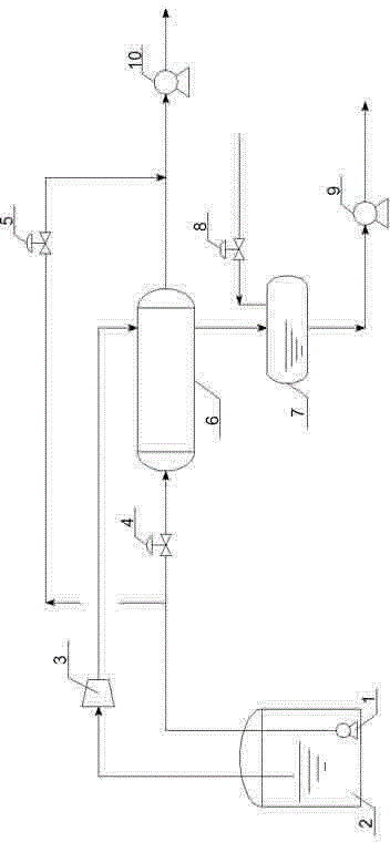
[0020] Treatment unit with a low-pressure BOG compressor;

[0021] The BOG processing device used in the normal operating conditions of the LNG receiving station includes an LNG storage tank 2, a low-pressure BOG compressor 3, a plate-shell LNG / BOG heat exchanger 6, and a BOG condensate buffer tank 7, and the LNG storage tank 2 A gas phase outlet pipeline is connected to a low-pressure BOG compressor 3, and the outlet pipeline of the low-pressure BOG compressor 3 is connected to the LNG / BOG heat exchanger 6. There are two outlet pipelines of the LNG / BOG heat exchanger 6, one of which is connected to the LNG high-pressure pump 10 is connected, and the other is connected with the BOG condensate buffer tank 7, and the outlet pipeline of the BOG condensate buffer tank 7 is connected with the booster pump 9; the BOG condensate buffer tank 7 is connected with the nitrogen supply pipeline, and a regulating valve is arranged on the nitrogen supply pipeline Three 8; LNG low-pressure pu...

Embodiment 2

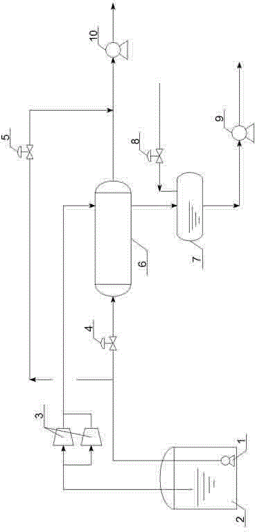
[0028] A treatment unit with two low-pressure BOG compressors arranged in parallel;

[0029] The BOG processing device used in the normal operating conditions of the LNG receiving station includes an LNG storage tank 2, a low-pressure BOG compressor 3, a shell-and-tube LNG / BOG heat exchanger 6 and a BOG condensate buffer tank 7, and the LNG storage tank 2 A gas phase outlet pipeline is connected with two low-pressure BOG compressors 3 arranged in parallel, and the outlet pipeline of the low-pressure BOG compressor 3 is connected with the LNG / BOG heat exchanger 6. There are two outlet pipelines of the LNG / BOG heat exchanger 6, one of which is connected with the The LNG high-pressure pump 10 is connected, the other is connected with the BOG condensate buffer tank 7, and the outlet pipeline of the BOG condensate buffer tank 7 is connected with the booster pump 9; the BOG condensate buffer tank 7 is connected with the nitrogen replenishment pipeline, and the nitrogen replenishment ...

Embodiment 3

[0036] A processing unit with three low-pressure BOG compressors arranged in parallel;

[0037]The BOG processing device used in the normal operating conditions of the LNG receiving station includes an LNG storage tank 2, a low-pressure BOG compressor 3, a plate-fin LNG / BOG heat exchanger 6 and a BOG condensate buffer tank 7, and the LNG storage tank 2 A gas phase outlet pipeline is connected with three low-pressure BOG compressors 3 arranged in parallel, and the outlet pipeline of the low-pressure BOG compressor 3 is connected with the LNG / BOG heat exchanger 6. There are two outlet pipelines of the LNG / BOG heat exchanger 6, one of which is connected with the The LNG high-pressure pump 10 is connected, the other is connected with the BOG condensate buffer tank 7, and the outlet pipeline of the BOG condensate buffer tank 7 is connected with the booster pump 9; the BOG condensate buffer tank 7 is connected with the nitrogen replenishment pipeline, and the nitrogen replenishment p...


PUM


Abstract

The invention discloses a BOG (boil-off gas) treatment process and device under normal operation condition of an LNG (liquefied natural gas) receiving station. The treatment process includes the steps: conveying BOG from an LNG storage tank into a low-pressure BOG compressor, pressurizing the BOG to reach 0.5-0.8MPaG, reaching the outlet temperature of 0-5 DEG C and then enabling the BOG to enter an LNG / BOG heat exchanger; conveying LNG into the LNG / BOG heat exchanger by a low-pressure LNG pipeline from an LNG low-pressure pump, exchanging heat with the BOG at an outlet of the low-pressure BOG compressor and finally condensing the BOG into liquid; enabling condensed BOG condensate to a BOG condensate buffer tank; arranging a nitrogen pipeline on the BOG condensate buffer tank and maintaining the pressure of the buffer tank at 0.6MPaG; enabling the condensate from the BOG condensate buffer tank to enter a pressurizing pump, pressurizing the condensate to reach 1.0MPaG, conveying the condensate to an LNG tank car for loading, and treating the BOG. The treatment process has the advantages of reasonable design, simplicity in control, easiness in operation, convenience in mounting and the like, a horizontal LNG / BOG shell-and-tube or shell-and-plate heat exchanger replaces a previous overhead re-condenser, construction difficulty is greatly reduced, and safety can be improved.

Description

technical field [0001] The invention relates to the field of BOG processing of LNG receiving stations, in particular to a BOG processing process and device used for LNG receiving stations under normal operating conditions. Background technique [0002] LNG (Liquefied Natural Gas) is the abbreviation of liquefied natural gas, it makes full use of natural gas at normal pressure and -162 o After liquefaction at C, the volume can be reduced to 1 / 600 of the gaseous state, which provides a new way for the efficient transportation of natural gas and expands the application field of natural gas. According to the national energy plan, the proportion of natural gas in energy consumption is increasing year by year, and it is expected to account for about 10% of the entire energy structure by 2020. [0003] LNG is an ultra-low temperature liquid. Although the storage tank has a good cold and heat insulation function during storage, it is still inevitable that heat will be introduced in...

Claims


Application Information

Patent Timeline
Patent Type & Authority Applications(China)
IPC IPC(8): F17C13/04F17C13/00F17D1/00
Inventor 仇德朋苗兴旺徐国峰曲顺利赵彩云郭雷朱艳艳鹿晓斌张华伟
Owner CHINA NAT OFFSHORE OIL CORP
Why Eureka
Try Eureka