Dehumidifier

A technology for dehumidifiers and wet areas, applied in the field of dehumidifiers installed with heat pumps, can solve the problems of inability to achieve step temperature rise, limited heating efficiency of condensers, etc., and achieve the effect of flexible use and power reduction

Inactive Publication Date: 2015-09-16
JIANGSU SUJING GROUP
View PDF3 Cites 8 Cited by
  • Summary
  • Abstract
  • Description
  • Claims
  • Application Information

AI Technical Summary

Problems solved by technology

However, the heating efficiency of the condenser in the regeneration channel of the dehum

Method used


Image

  • Dehumidifier
  • Dehumidifier

Examples


Embodiment Construction

[0013] The present invention will be described in further detail below in conjunction with specific examples. It should be understood that these embodiments are used to illustrate the basic principles, main features and advantages of the present invention, and the present invention is not limited by the scope of the following embodiments. The implementation conditions used in the examples can be further adjusted according to specific requirements, and the unspecified implementation conditions are usually the conditions in routine experiments.

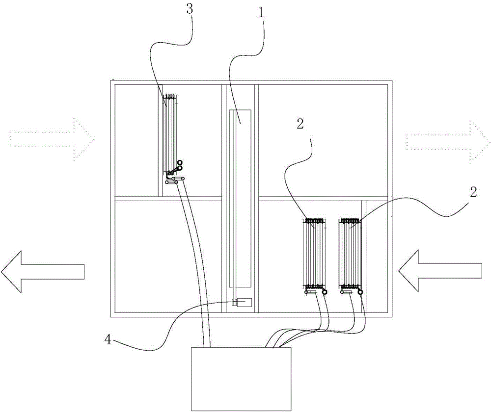
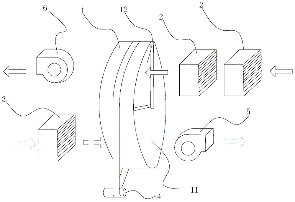
[0014] Such as figure 1 Shown is a dehumidifier with a heat pump according to the present invention. The dehumidifier includes a dehumidification wheel 1, an adsorbent is arranged on the dehumidification wheel 1, and a dehumidification zone 11 and a regeneration zone are separated on the dehumidification wheel 1. Zone 12, the dehumidification wheel 1 is connected with a driving device 4 to drive it to rotate. The side of the dehum...


PUM


Abstract

The invention relates to a dehumidifier comprises a dehumidifying wheel. An absorbent is arranged on the dehumidifying wheel; the dehumidifying wheel is divided into a dehumidifying area and a regeneration area; the dehumidifying wheel is connected with a driving device driving the same to rotate; one side of the dehumidifying area is provided with a fresh air duct; one side of the regeneration area is provided with a regenerating air duct; the dehumidifier further comprises at least two heat pumps; each heat pump is formed by a steamer, a compressor, a condenser and an expansion valve altogether forming a refrigerating circulating system; condensers of a plurality of heat pumps are arranged on a regeneration air inlet of the regeneration area; and the condensers of the plurality of heat pumps are orderly arranged front and back in the regeneration air duct. The numbers of heat pumps can be determined as needed; one or a plurality of heat pumps of the dehumidifier can be opened or closed as needed, so the dehumidifier can meet needs of various conditions; and flexible use can be achieved.

Description

technical field [0001] The invention relates to a dehumidifier, in particular to a dehumidifier equipped with a heat pump. Background technique [0002] At present, the dehumidification and regeneration part of the rotary dehumidifier on the market adopts electric heating, steam heating or natural gas indirect heating. 140°C, high energy consumption; the surface cooler for fresh air is provided with chilled water by the refrigerator, and the energy consumption of the whole machine is quite large. In civil air defense, national defense, swimming pools and other occasions, the humidity load is large, especially in summer, and general air conditioners cannot meet the dehumidification requirements. In the prior art, a dehumidifier equipped with a heat pump is also provided, and the condenser using the heat pump is placed in the regeneration channel The regeneration air is heated inside, and the evaporator is placed in the fresh air channel to cool the fresh air. However, the h...

Claims


Application Information

Patent Timeline
IPC IPC(8): F24F3/14
CPCY02B30/52F24F3/14F24F2003/1464
Inventor 房爱军宁金伟傅兴彬桑希惠仝顺
Owner JIANGSU SUJING GROUP
Why Eureka
Try Eureka