A test bench for movable tooth continuously variable transmission

A continuously variable transmission, test bench technology, applied in the direction of machine gear/transmission mechanism testing, etc., can solve the problems of unknown system performance and parameters

Inactive Publication Date: 2018-02-27
BEIJING UNIV OF TECH +1
View PDF12 Cites 0 Cited by
  • Summary
  • Abstract
  • Description
  • Claims
  • Application Information

AI Technical Summary

Problems solved by technology

Due to the innovative structure and principle of this type of transmission, its system performance and parameters are unknown. At present, there is no test system that can test the performance of this new type of transmission.
In addition, test benches for testing traditional transmissions are usually driven by a single power source, and usually only static characteristic tests can be completed on the same bench

Method used


Image

  • A test bench for movable tooth continuously variable transmission

Examples


Embodiment Construction

[0017] The present invention will be further described below in conjunction with accompanying drawing:

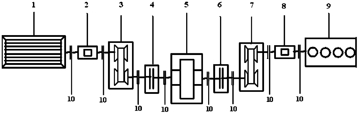
[0018] A test bench for a movable-tooth continuously variable transmission is characterized in that it includes a motor 1, a first and a second rotational speed torque sensor, a first movable-tooth continuously variable transmission 3, a first electromagnetic clutch 4, a dynamometer 5, The second electromagnetic clutch 6, the second movable tooth continuously variable transmission 7, the second rotational speed torque sensor 8, and the engine 9 are connected by couplings between these nine components.

[0019] see figure 1 , the motor and the first movable-tooth continuously variable transmission are connected through the first rotational speed torque sensor, and the first rotational speed torque sensor can collect the output rotational speed and torque of the motor (that is, the input rotational speed and rotational speed of the first movable-tooth continuously variable tr...


PUM


Abstract

A test bench for a movable-tooth continuously variable transmission includes main components such as an engine, a motor, a speed torque sensor, an electromagnetic clutch, a dynamometer, and a movable-tooth continuously variable transmission. The dynamometer can realize forward and reverse rotation work, and its two ends are designed with electromagnetic clutch structure, which can make the test and test at both ends of the dynamometer not interfere with each other; it is designed with two driving devices of engine and motor, through connection and disconnection Opening the clutch can realize the performance matching test verification of the movable tooth CVT separately from the motor and the engine; realize the static and dynamic tests of the movable tooth CVT, when the electromagnetic clutch at the motor end is disconnected, and the electromagnetic clutch at the engine end is combined. The static test test of the movable tooth CVT, when the electromagnetic clutches at the motor end and the engine end are both engaged, it is the dynamic test test of the movable tooth CVT. At this time, the motor is used as the electric inertia, which can simulate the inertia of different models. The whole system has perfect functions, compact layout and simple test scheme.

Description

technical field [0001] The invention relates to a test technology of a movable-tooth continuously variable transmission, in particular to a test bench for system performance of a movable-tooth continuously variable transmission. Background technique [0002] The movable tooth continuously variable transmission belongs to a new type of continuously variable transmission device in the field of continuously variable transmission. This movable tooth continuously variable transmission is a non-friction deformation movable tooth continuously variable transmission device. The friction / traction transmission is a new type of movable tooth stepless meshing transmission method, which can realize high-power transmission. Due to the innovation of the structure and principle of this kind of transmission, its system performance and parameters are unknown, and there is no test system that can test the performance of this new type of transmission. In addition, the test benches for testing t...

Claims


Application Information

Patent Timeline
Patent Type & Authority Patents(China)
IPC IPC(8): G01M13/02
Inventor 冯能莲米磊康常涛宾洋
Owner BEIJING UNIV OF TECH
Why Eureka
Try Eureka