Optical coupling module
A technology of optical coupling and rod body, which is applied in the field of optical coupling modules, can solve the problems of increasing the volume of connecting parts, which are complicated, impossible to talk about, impact resistance, drop difference, etc., achieve good anti-deformation effect, ensure the fixing effect, and improve the mechanical strength. Effect
- Summary
- Abstract
- Description
- Claims
- Application Information
AI Technical Summary
Problems solved by technology
Method used
Image
Examples
Embodiment 1
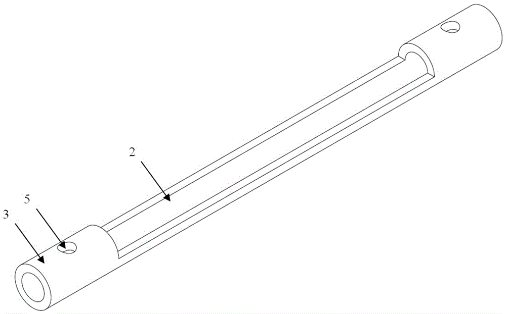
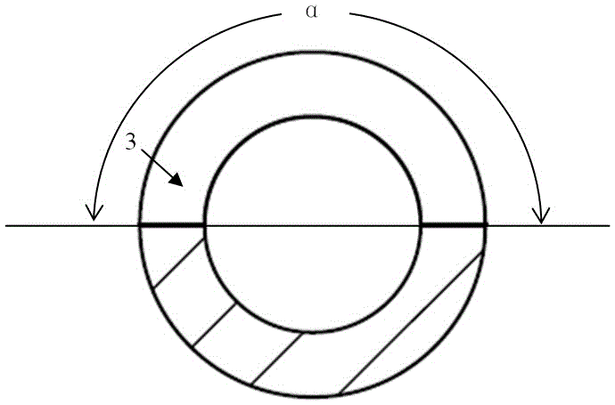
[0041] see figure 1 , the optical coupling module, whose shaft is in the shape of a cylindrical tube; there is a notch 2 on the top of the optical coupling module along the long axis, see figure 2 ; The length L2 of the notch 2 is between 10-1600mm; the angle α between the two long sides of the notch 2 is between 160° and 210°, see image 3 The two ends of the optical coupling module are the coupling fixing cylinder 3 for fixing the collimator 1, and the coupling fixing cylinder 3 is provided with a through positioning hole 5. The preferred solution is to open a pair of positioning holes 5 in the vertical direction and horizontal direction of the coupling and fixing cylinder 3, and match with adjusting nuts to fine-tune and position the collimator 1 .
Embodiment 2
[0043] see Figure 4 , the optical coupling module, whose shaft is in the shape of a cylindrical tube; there is a notch 2 on the top of the optical coupling module along the long axis, see figure 2 ; The length L2 of the notch 2 is between 10-80mm; the angle α between the two long sides of the notch 2 is between 190° and 210°, see image 3 The two ends of the optical coupling module are the coupling fixing cylinder 3 for fixing the collimator, and the coupling fixing cylinder 3 is provided with through positioning holes 5 . see Figure 5 , Mesh cylinders 6 are provided in the coupling and fixing cylinders 3 . see Figure 6 , insert the collimator 1 covered with the mesh tube 6 on the tube wall into the coupling and fixing tube 3 respectively, after adjusting and coupling the collimator 1 on both sides, and then drip 5 glue from the positioning hole, the glue is in the alignment Under the action of the siphon between the collimator 1, the mesh cylinder 6 and the coupling a...
Embodiment 3
[0046] see Figure 7 , the optical coupling module, whose shaft is in the shape of a cylindrical tube; there is a notch 2 on the top of the optical coupling module along the long axis, see figure 2 ; The length L2 of the notch 2 is between 10-1600mm; the angle α between the two long sides of the notch 2 is between 160° and 210°, see Figure 9 The two ends of the optical coupling module are the coupling fixing cylinder 3 for fixing the collimator, and the coupling fixing cylinder 3 is provided with through positioning holes 5 . see Figure 8 , there is a shallow groove 7 along the long axis direction at the bottom of the rod body of the optical coupling module. Figure 9 .
PUM
 Abstract
Description
Claims
Application Information
 - R&D
- Intellectual Property
- Life Sciences
- Materials
- Tech Scout
- Unparalleled Data Quality
- Higher Quality Content
- 60% Fewer Hallucinations
Browse by: Latest US Patents, China's latest patents, Technical Efficacy Thesaurus, Application Domain, Technology Topic, Popular Technical Reports.
© 2025 PatSnap. All rights reserved.Legal|Privacy policy|Modern Slavery Act Transparency Statement|Sitemap|About US| Contact US: help@patsnap.com


