IC card control terminal of building concentrator in heating system

A heat supply system and concentrator technology, applied in the direction of electrical program control, signal transmission system, comprehensive factory control, etc., can solve problems such as large-area operation failure, inability to intuitively understand the valve opening and closing status, heat valve control failure, etc. Achieve the effects of solving the delay of uploading data, humanizing heating management, and reducing workload

Active Publication Date: 2019-01-15
LANZHOU HUAFANG INTELLIGENCE TECH
View PDF8 Cites 0 Cited by
  • Summary
  • Abstract
  • Description
  • Claims
  • Application Information

AI Technical Summary

Problems solved by technology

However, this method has the following disadvantages: first, because the door of the pipe well is usually locked, when a resident needs to recharge the valve, the heat supply unit must send someone to open the door of the pipe well, which is very inconvenient; Second, the heating unit cannot intuitively understand the opening and closing status of the valve of a certain household. When the valve of a certain household fails to close, the heating unit cannot know in time, which will cause heat loss to the heating unit; When the remaining calorific value is insufficient, residents cannot know in time, which brings inconvenience to users
The concentrator is a bridge for data transmission, which not only transmits data to the main control center, but also executes the control instructions sent by the main control center; however, due to factors such as interference and transmission distance of the GPRS signal during transmission, the communication will be unstable. When the concentrator reports data to the main control center, there will be interruptions, delays, and even errors. Sometimes errors will occur when executing the instructions of the main control center. For example, the control of the thermal valve often fails, and it is easy to cause large-scale operation failures. Both for heating units and households, there may be losses

Method used


Image

  • IC card control terminal of building concentrator in heating system
  • IC card control terminal of building concentrator in heating system
  • IC card control terminal of building concentrator in heating system

Examples


Embodiment Construction

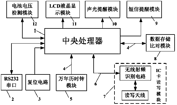
[0023] Such as figure 1 , figure 2 As shown, the IC card control terminal of the heating system building concentrator includes the central processing unit 1, the RS232 serial port 2, the reset circuit 3, the perpetual calendar clock module 5, the IC card reading and writing module 7, and the data storage comparison module 8. Short message reminder module 9, sound and light reminder module 10, LCD liquid crystal display module 11, battery voltage detection module 12.

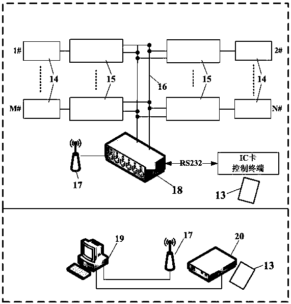
[0024] The central processing unit 1 is connected to the RS232 serial port 2, the reset circuit 3, the perpetual calendar clock module 5, the IC card reading and writing module 7, the data storage comparison module 8, the short message reminding module 9, the sound and light reminding module 10, the LCD liquid crystal display module 11, The battery voltage detection module 12 is connected; the RS232 serial port 2 is connected to the building concentrator 18, which is connected to the array heat metering device in th...


PUM


Abstract

The present invention relates to a heat supply system building concentrator IC card control terminal, which comprises a central processor, a RS232 serial port, a reset circuit, a calendar clock module, an IC card reading and writing module, a data storage comparison module, a short message reminding module, a sound and light reminding module, an LCD liquid crystal display module, and a battery voltage detection module, wherein the central processor is respectively connected with the RS232 serial port, the reset circuit, the calendar clock module, the IC card reading and writing module, the data storage comparison module, the short message reminding module, the sound and light reminding module, the LCD liquid crystal display module, and the battery voltage detection module, the RS232 serial port is connected with a building concentrator, the building concentrator is connected with plural groups of heat metering devices, the IC card reading and writing module is matched with a reading writer, the reading writer and the IC card reading and writing module are respectively provided with a matched IC card, the reading writer is connected to a PC machine, the PC machine is connected with the building concentrator through GPRS, and the LCD liquid crystal display module is externally connected with a liquid crystal display screen. With the heat supply system building concentrator IC card control terminal of the present invention, the heat supply system control is flexible and reliable.

Description

Technical field [0001] The invention relates to the field of automatic meter reading and charging management and control of a heating system, in particular to an IC card control terminal of a building concentrator of a heating system. Background technique [0002] In recent years, with the continuous advancement of national energy conservation and emission reduction work, new buildings in northern my country have basically installed heat meters, and the heat metering and renovation of existing buildings has also been vigorously promoted. The mode of charging heating fee is changed to charge according to the measured value of the heat meter. For residents, more heat is used to pay more, and less heat is used to pay less, which saves costs; for heating units, it saves energy consumption and benefits the country and the people. But at the same time it also brings a problem, that is, the difficulty of charging. [0003] At present, the heating company can only copy the household's hea...

Claims


Application Information

Patent Timeline
Patent Type & Authority Patents(China)
IPC IPC(8): G08C19/00G05B19/418G07F15/06
Inventor 张引龙何博侠张廷江杨洪锋薛蓉刘若琳李春雷
Owner LANZHOU HUAFANG INTELLIGENCE TECH
Why Eureka
Try Eureka