Infrared emission structure, infrared remote controller and infrared remote control method

An infrared transmitter, infrared remote control technology, applied in instruments, signal transmission systems, non-electrical signal transmission systems, etc., can solve problems such as user inconvenience and repeated reception, improve accuracy, reduce instantaneous power consumption, reduce The effect of low energy consumption

Inactive Publication Date: 2015-09-16
GD MIDEA AIR-CONDITIONING EQUIP CO LTD +1
View PDF6 Cites 14 Cited by
  • Summary
  • Abstract
  • Description
  • Claims
  • Application Information

AI Technical Summary

Problems solved by technology

However, if the method of multi-channel time-sharing code transmission is adopted, although the instantaneous power of the remote control can be reduced, the multi-directional time-sharing code transmission will cause the receiving end of the home appliance to repeatedly receive the remote control code, so that the home appliance will respond multiple times. will cause great inconvenience to users

Method used


Image

  • Infrared emission structure, infrared remote controller and infrared remote control method
  • Infrared emission structure, infrared remote controller and infrared remote control method
  • Infrared emission structure, infrared remote controller and infrared remote control method

Examples


Embodiment Construction

[0044] In order to understand the above-mentioned purpose, features and advantages of the present invention more clearly, the present invention will be further described in detail below in conjunction with the accompanying drawings and specific embodiments. It should be noted that, in the case of no conflict, the embodiments of the present application and the features in the embodiments can be combined with each other.

[0045] In the following description, many specific details are set forth in order to fully understand the present invention. However, the present invention can also be implemented in other ways different from those described here. Therefore, the protection scope of the present invention is not limited by the specific details disclosed below. EXAMPLE LIMITATIONS.

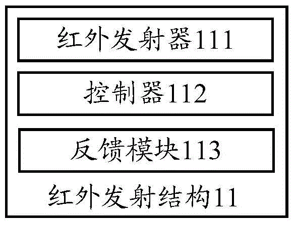
[0046] figure 1 A block diagram of an infrared emitting structure according to one embodiment of the invention is shown.

[0047] An infrared emission structure 11 proposed in the embodiment of the...


PUM


Abstract

Theinvention provides an infrared emission structure, an infrared remote controller and an infrared remote control method. The infrared emission structure comprises a plurality of infrared emitters, a controller and a feedback module, wherein the infrared emitters are distributed at multiple positions of the infrared remote controller and are used for emitting infrared codes in a circulating manner according to the preset sequence; the controller is arranged inside the infrared remote controller, is connected with the plurality of infrared emitters, and is used for controlling the plurality of infrared emitters to emit the infrared codes in a circulating manner; the feedback module is connected with the controller, is used for acquiring the controlled feedback information from controlled equipment of the infrared remote controller, and feeding back the controlled feedback information to the controller, so that the controller can be used for controlling the plurality of infrared emitters to stop emitting the infrared codes in a circulating manner according to the controlled feedback information. According to the technical scheme, multi-direction operation control of the infrared remote controller can be achieved, the instantaneous code emitting power of the infrared remote controller can be reduced, the power consumption is saved, the problem that electric equipment repeatedly responds after repeatedly receiving the control information can be avoided, and the practicability of the infrared remote controller can be enhanced.

Description

technical field [0001] The invention relates to the technical field of electrical remote control, in particular to an infrared emitting structure, an infrared remote control and an infrared remote control method. Background technique [0002] At present, the infrared remote controllers of ordinary household appliances generally have only one infrared emitter, and the infrared emitter has a certain directionality. Control, when the transmitter direction of the remote control deviates from the direction of the electrical equipment, it is often necessary to adjust the direction of the remote control and press the button several times to achieve effective control. [0003] In order to solve this problem, the usual method is to increase the number of infrared emitting circuits, or adopt some specific spatial layouts for the infrared emitting heads to achieve multi-directional or omnidirectional infrared control. However, these solutions often use the method of sending codes at t...

Claims


Application Information

Patent Timeline
Patent Type & Authority Applications(China)
IPC IPC(8): G08C23/04
Inventor 谭斌区志财
Owner GD MIDEA AIR-CONDITIONING EQUIP CO LTD
Why Eureka
Try Eureka