Plug-in combination of devices

A plug-in module and contact head technology, which is applied to the parts of the connection device, coupling device, connection, etc., to achieve the effect of simple manufacturing and high mechanical load capacity

Inactive Publication Date: 2015-09-16
PHOENIX CONTACT GMBH & CO KG
View PDF7 Cites 2 Cited by
  • Summary
  • Abstract
  • Description
  • Claims
  • Application Information

AI Technical Summary

Problems solved by technology

This way of locking the plug-in module in the device base has the disadvantage that in order to lock and unloc

Method used


Image

  • Plug-in combination of devices
  • Plug-in combination of devices
  • Plug-in combination of devices

Examples


Embodiment Construction

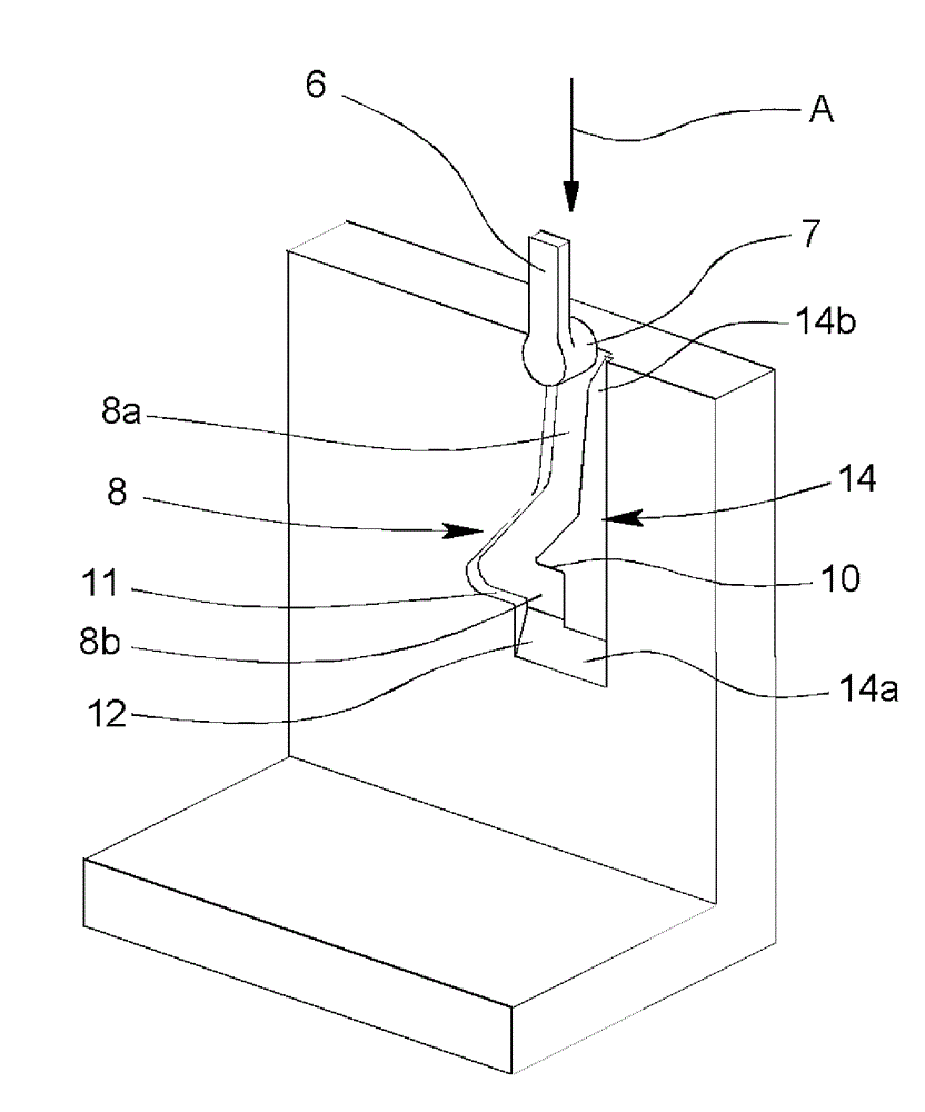
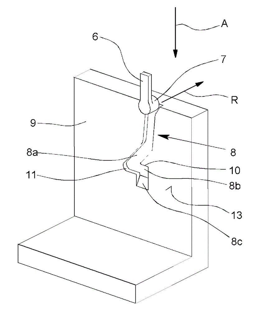
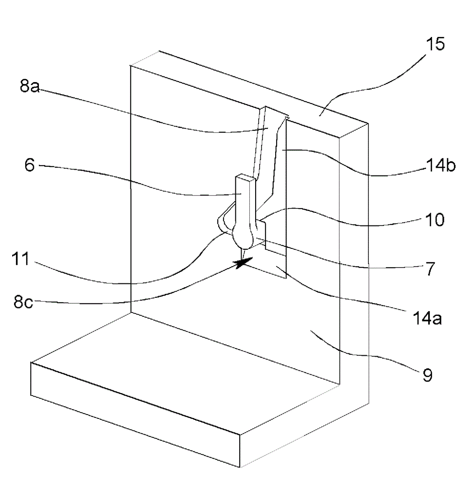
[0034] 1 to 3 show simplified representations of an exemplary embodiment of a pluggable device combination according to the invention for protection against grid overvoltages or overcurrents. The pluggable device combination includes an approximately U-shaped device base 1 and a plug-in module 2 that can be inserted into the device base 1 . The device base 1 has a base housing 3 with a recess 4 for receiving a plug-in module 2 . Connecting terminals, not shown here, for example screw terminals, are arranged in the two legs of the device base 1 in order to connect conductors of the network to be protected. The connection terminals are electrically conductively connected to plug contacts, via which the plug-in module 2 can be electrically connected to the device base 1 when the plug-in module 2 is plugged onto the device base 1 . For this purpose, the plug-in module 2 has coupling plug contacts corresponding to the plug contacts. As is customary in the prior art, the plug cont...


PUM


Abstract

The present invention relates to a plug-in apparatus combination with an apparatus base and a plug-in module, wherein, the plug-in module can be plugged into the apparatus base. The apparatus base has a base housing with a recess for receiving the plug-in module, a linkage terminal for a conductor of a power grid to be protected, and a plug-in contact linked with the linkage terminal. The plug-in module has a plug housing, a protective element arranged in the plug-in housing, and a linkage plug-in contact corresponding to the plug-in contact. In the apparaut combination, locking and replacement of the plug-in module are executed thereby, namely, a latching linkage portion acting between the apparatus base and the plug-in module has a latching arm with a latching mechanism and a groove, the latching linkage portion is arranged on the wall opposite to the latching arm, a latching hook of the latching arm is used for guding when the plug-in module is plugged into the apparatus base. The groove has a first region, a second region, and a third region, and the deepth of the groove is too small in the end of the third region so that the latching hook does not guide in the groove.

Description

technical field [0001] The invention relates to a pluggable device combination (Gerötekombination) for protection against grid overvoltages or overcurrents, with a device base and at least one plug-in module that can be plugged onto the device base, wherein the device base The socket has: a basic housing with a recess for receiving a plug-in module; a connection terminal for a conductor of the network to be protected; and a plug contact connected to the connection terminal, wherein the plug-in module has a plug housing; protective elements arranged in the plug housing, in particular lightning current and / or overvoltage conductors; and coupling plug contacts corresponding to the plug contacts, and wherein at least one connection between the Functional snap-fit ​​connection between modules. Background technique [0002] Of particular importance for the operational reliability of electrical installations, machines and installations is a long-term, defined supply of energy. Fo...

Claims


Application Information

Patent Timeline
IPC IPC(8): H01R13/639
CPCH01T4/04H01T4/06H01R13/639H01R13/514
Inventor T.迈尔S.普费特纳
Owner PHOENIX CONTACT GMBH & CO KG
Why Eureka
Try Eureka