
Corrugated or pleated flat material

a flat material and corrugated technology, applied in the field of corrugated or pleated flat materials, can solve the problems of increasing the pressure loss experienced the pressure loss sustained by the fluid flowing through, and the pleats or corrugations coming, so as to reduce the flow loss, increase the mechanical load-bearing capacity of the combination of functional layer and supporting fabric, and reduce the effect of throughflow resistan

Active Publication Date: 2012-08-28
ARGO HYTOS GRP AG
View PDF34 Cites 2 Cited by
  • Summary
  • Abstract
  • Description
  • Claims
  • Application Information

AI Technical Summary

Benefits of technology

"The invention relates to a flat material that can be used as a corrugated or pleated fabric. The invention involves making the supporting fabric deformable, which increases its mechanical load-bearing capacity and reduces the risk of damage under changing pressure loads. The supporting fabric is made of a twill weave, which creates stable micro-channels that allow fluid to flow through with very low flow losses. The invention also involves using a twill weave for the supporting fabric, which allows for the formation of stable micro-channels and reduces the throughflow resistance of the flat material. The flat material can be mechanically supported at the end faces of the bellows and a supporting tube can be used to support the flat material on the outflow side. The invention also involves using metal threads to discharge static charges and prevent static charging of the supporting fabric and flat material as a whole. The threads running parallel to the pleats or corrugations are produced from metal and the threads running perpendicular to the pleats or corrugations are produced from a plastics material."

Problems solved by technology

The loading of the flat material by the fluid flowing through may, however, have the consequence that the pleats or corrugations come to lie in close abutment against one another, in particular on the outflow side of the flat material.
This increases the throughflow resistance of the flat material and consequently the pressure loss sustained by the fluid flowing through.
For this purpose, however, relatively thick filaments are required for the supporting layer, which is formed as a woven fabric, and this once again increases the pressure loss experienced by the fluid flowing through.
Furthermore, in the case of flat materials of this kind, there is the risk of the materials suffering mechanical impairment, for example by formation of cracks, in particular under changing pressure loads.
A further disadvantage is that, with a configuration of this kind, only sinterable functional layers can be used.
This is a relatively complex construction that entails not inconsiderable production costs.

Method used


Image

  • Corrugated or pleated flat material
  • Corrugated or pleated flat material
  • Corrugated or pleated flat material

Examples


Embodiment Construction

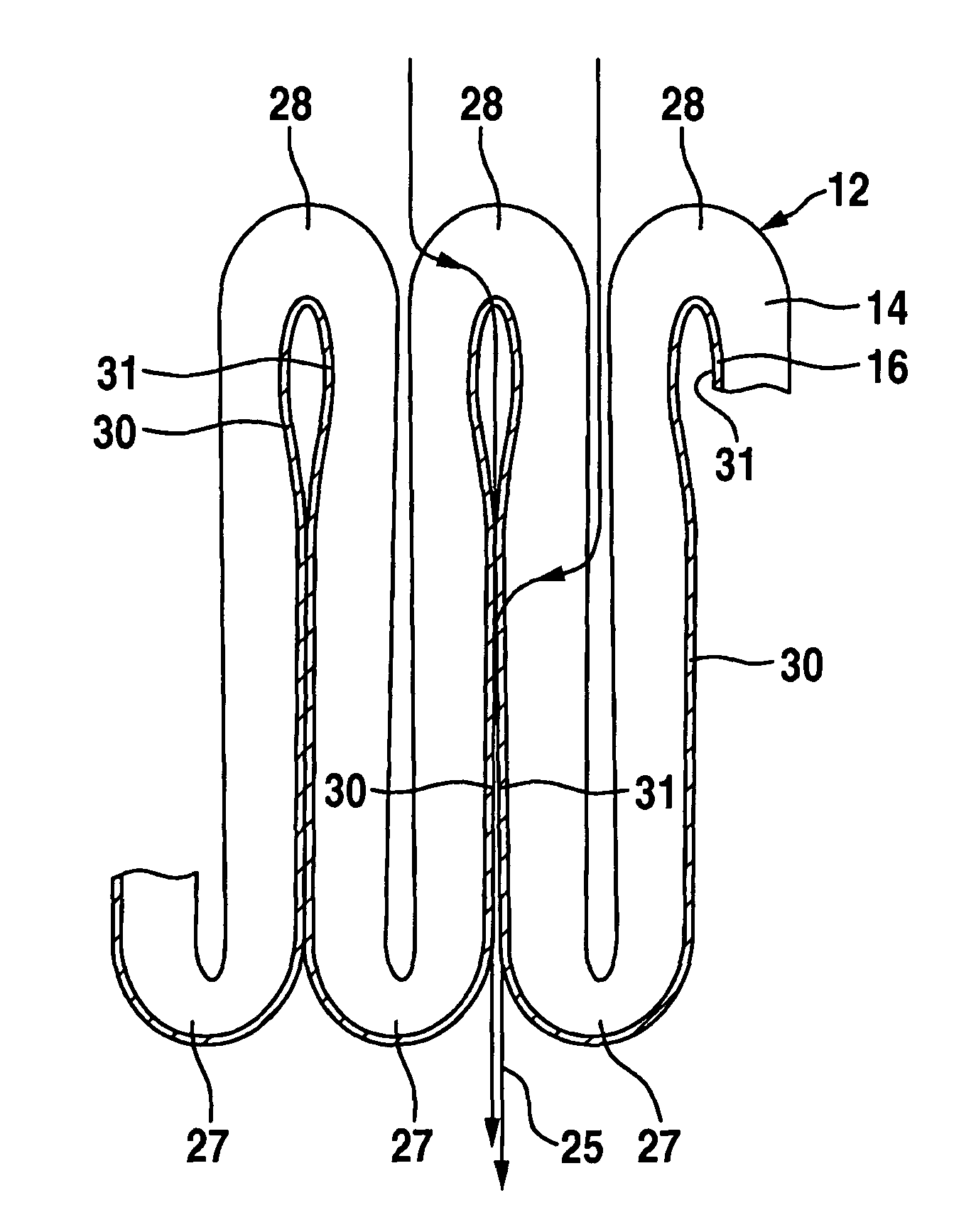
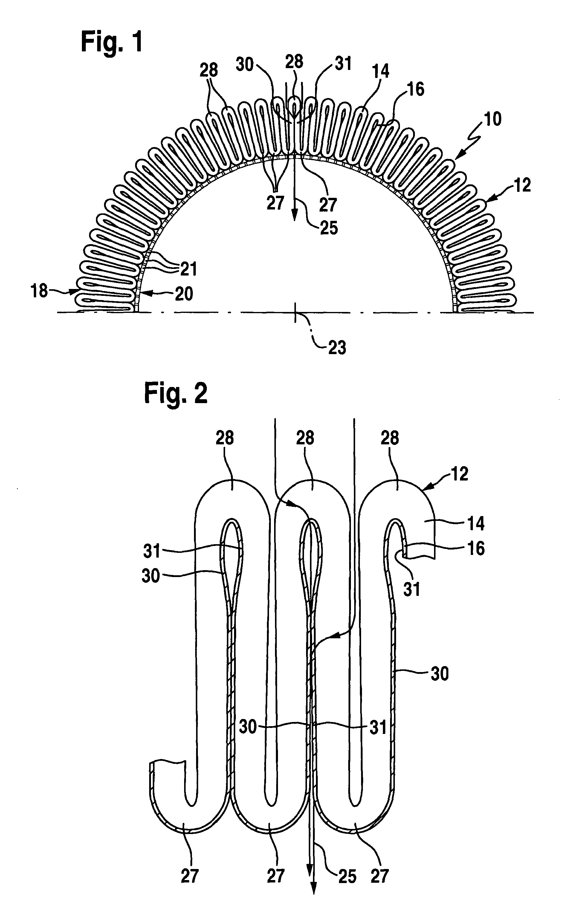
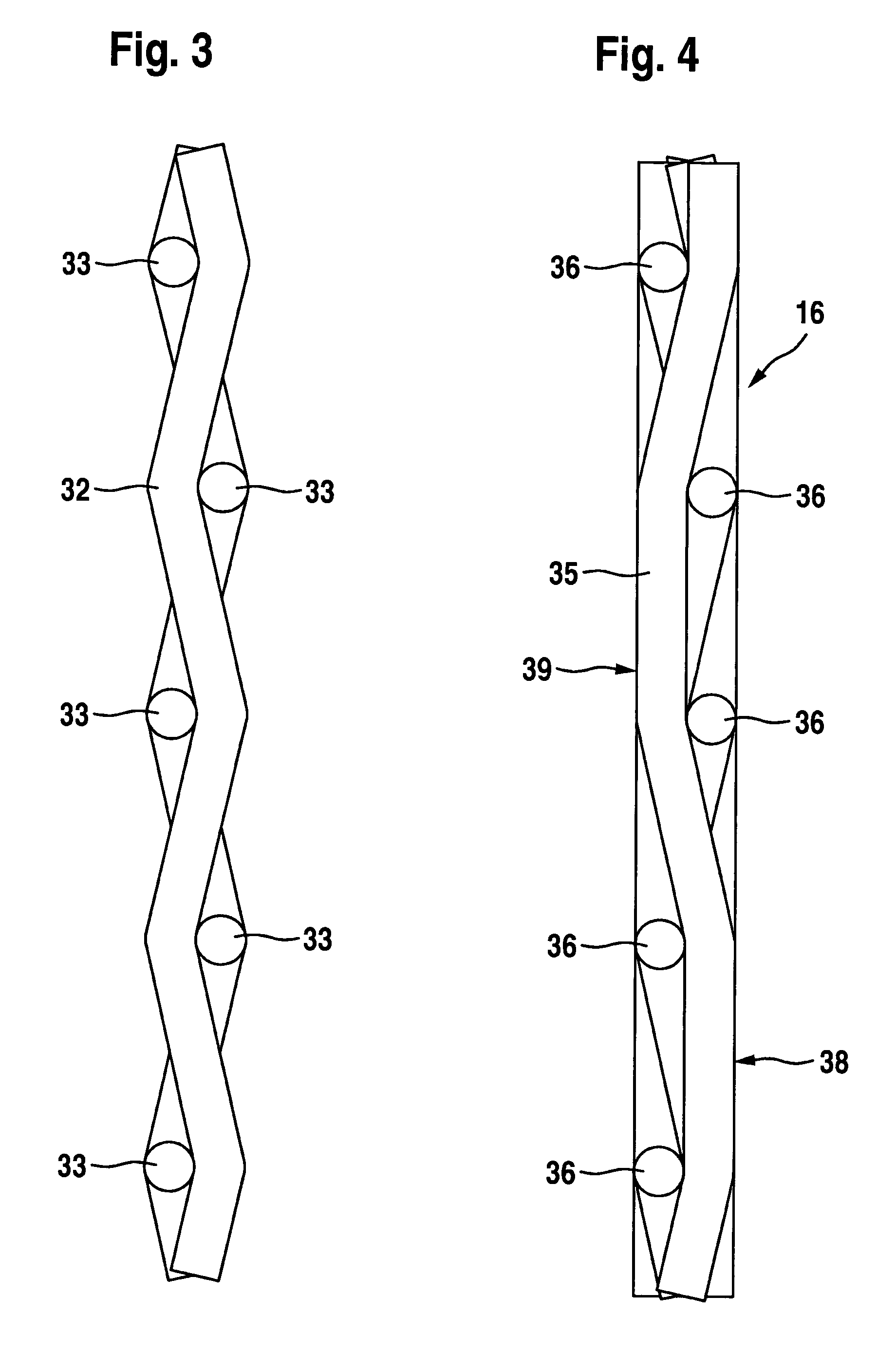
[0042]In FIG. 1, a filter element 10 is illustrated in a purely schematic representation, with a flat material 12 pleated in a star-like manner and, as clearly revealed by FIG. 2, comprising a functional layer in the form of a filter layer 14 and a supporting layer in the form of a supporting fabric 16. The pleated flat material 12 forms a hollow-cylindrical, circumferentially closed bellows 18, only half of which is represented in FIG. 1 to achieve a better overview. The bellows 18 is supported on the inside on a supporting tube 20, which has a multiplicity of apertures 21. The longitudinal axis of the supporting tube 20 is aligned coaxially with the cylinder axis 23 of the bellows 18.

[0043]The filter layer 14 is preferably of a multi-ply form and comprises a fine filter layer of a nonwoven material, which is covered on both sides by a coarse filter layer. A filter layer of this kind is known per se to the person skilled in the art, for which reason the multi-ply configuration of t...


PUM

PropertyMeasurementUnit
particle sizeaaaaaaaaaa
widthaaaaaaaaaa
widthaaaaaaaaaa

Abstract

The invention relates to a corrugated or pleated flat material with a plurality of pleats or corrugations that run parallel to one another and successively define a pleat or corrugation peak and a pleat or corrugation valley, the peak and valley being connected to one another by way of a pleat or corrugation flank, wherein a fluid can flow through the flat material and the flat material has at least one deformable functional layer which rests on a supporting layer in the direction of throughflow of the fluid, said supporting layer comprising a supporting fabric, the functional layer allowing foreign substances to be removed from or delivered to the fluid. In order to develop the flat material in such a way that it has greater mechanical load-bearing capacity and lower resistance to throughflow, it is proposed according to the invention that the supporting fabric is deformable and comprises a twill weave. Furthermore, the use of a supporting fabric of this kind for providing support on the outflow side for a pleated or corrugated functional layer is proposed.

Description

[0001]This application is a continuation of international application number PCT / EP2008 / 004929 filed on Jun. 19, 2008.[0002]The present disclosure relates to the subject matter disclosed in international application number PCT / EP2008 / 004929 of Jun. 19, 2008 and German application number 10 2007 040 892.9 of Aug. 24, 2007, which are incorporated herein by reference in their entirety and for all purposes.BACKGROUND OF THE INVENTION[0003]The invention relates to a corrugated or pleated flat material with a plurality of pleats or corrugations that run parallel to one another and successively define a pleat or corrugation peak and a pleat or corrugation valley, the peak and valley being connected to one another by way of a pleat or corrugation flank, wherein a fluid can flow through the flat material and the flat material has at least one deformable functional layer which rests on a supporting layer in the direction of throughflow of the fluid, said supporting layer comprising a supporti...

Claims


Application Information

Patent Timeline
Patent Type & Authority Patents(United States)
IPC IPC(8): B01D29/07B01D39/10B01D27/06
CPCB01D46/0036B01D46/521D03D11/00D03D13/008D03D15/00B01D29/21B01D39/083B01D39/086B01D46/103Y10T428/24694B01D2239/065B01D2239/0654B01D2239/069B01D2239/1216B01D2239/1233B01D2265/06D10B2101/20D10B2401/16D10B2505/04
Inventor SCHINDELIN, ANDREASSCHADT, WOLFRAM
Owner ARGO HYTOS GRP AG
Learn More