
Puncture drainage device

A drainage device and drainage tube technology, applied in the field of medical devices, can solve problems such as visceral injury, poor surgical results, and endanger the life of patients, and achieve the effect of ensuring surgical results and avoiding visceral injury or blood vessel bleeding.

Active Publication Date: 2015-09-23
SHANDONG UNIV QILU HOSPITAL
View PDF5 Cites 2 Cited by
  • Summary
  • Abstract
  • Description
  • Claims
  • Application Information

AI Technical Summary

Problems solved by technology

[0004] The drainage tube in the above-mentioned puncture drainage device is generally a straight hard tube, and the puncture needle is also made of metal material. The puncture needle is installed at the front end of the drainage tube. Once the puncture direction is determined, it is difficult to adjust it. , and forcibly changing the puncture direction will touch viscera or blood vessels, which will cause visceral damage or uncontrollable massive bleeding, resulting in poor surgical results and even endangering the patient's life

Method used


Image

  • Puncture drainage device
  • Puncture drainage device
  • Puncture drainage device

Examples


Embodiment 1

[0031] The invention provides a puncture drainage device, such as figure 1 As shown, including: puncture needle 1, drainage tube 2;

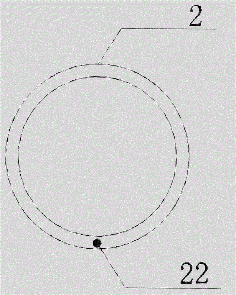
[0032] The puncture needle 1 is connected to the front end of the drainage tube 2; drainage holes 11 are distributed on the needle wall of the puncture needle 1, and the front end of the drainage tube 2 is provided with a movable joint 21 near the puncture needle 1, and the drainage A direction adjustment line 22 runs through the interlayer of the pipe wall of the pipe 2 , and the front end of the direction adjustment line 22 is connected to the movable joint 21 .

[0033] Wherein, in general, the diameter of the drainage tube 2 is much larger than that of the puncture needle 1, when the puncture needle 1 is directly installed on the front end of the drainage tube 2, there will be a connection step, in order to reduce the connection step caused by the puncture process. If there is tissue damage, the front end of the drainage tube 2 will adopt a...

Embodiment 2

[0040] Embodiment 2 of the present invention provides a puncture drainage device, such as Figure 4 As shown, including: puncture needle 1, drainage tube 2;

[0041] The puncture needle 1 is installed on the front end of the drainage tube 2; drainage holes 11 are distributed on the needle wall of the puncture needle 1, and the front end of the drainage tube 2 is provided with a movable joint 21 near the puncture needle 1. A direction adjustment line 22 runs through the interlayer of the tube wall of the drainage tube 2 , and the front end of the direction adjustment line 22 is connected to the movable joint 21 .

[0042] The drainage tube 2 includes: a cleaning tube 23 is arranged inside the drainage tube 2 ; the front end of the cleaning tube 23 is connected to the puncture needle 1 .

[0043] Wherein, the diameter of the cleaning tube 23 is smaller than that of the drainage tube 2, the cleaning tube 23 is placed inside the drainage tube 2, and the front end of the cleaning ...


PUM


Abstract

The invention discloses a puncture drainage device, and relates to the field of medical instruments. The puncture direction can be adjusted, visceral injuries or blood vessel bleeding is avoided, and the operation effect is ensured. The puncture drainage device comprises a puncture needle and a drainage tube, and the puncture needle is connected with the front end of the drainage tube. Drainage holes are distributed in the needle wall of the puncture needle, a movable joint is arranged at the position, close to the puncture needle, of the front end of the drainage tube, a direction adjusting line penetrates through a tube wall interlayer of the drainage tube, and the front end of the direction adjusting line is connected with the movable joint. The puncture drainage device is mainly used for guiding out hydrops in the body.

Description

technical field [0001] The invention relates to the field of medical instruments, in particular to a puncture drainage device. Background technique [0002] In clinical medicine, the main purpose of puncture surgery is to discharge a large amount of fluid in the patient's body or to extract fluid from the patient's body for testing. This operation mainly uses a puncture drainage device to drain or extract the body fluid, and the puncture drainage device can also extract Fluids from the patient's body are used to diagnose difficult and complex diseases. [0003] The puncture and drainage device used in the prior art is generally composed of a puncture needle and a drainage tube. The puncture needle is installed at the front end of the drainage tube. When using the puncture and drainage device for puncture, the puncture needle pulls the drainage tube to penetrate the skin and enter the body cavity At this time, the effusion in the body cavity is drained through the puncture a...

Claims


Application Information

Patent Timeline
IPC IPC(8): A61M1/00
CPCA61M1/00A61M1/842
Inventor 李峰胡三元王磊刘晗徐建威闫晔
Owner SHANDONG UNIV QILU HOSPITAL
Learn More