Remaining needle

An indwelling needle and needle seat technology, which is applied in the field of indwelling needles, can solve the problems of affecting the use time of the indwelling needle, affecting the performance of the indwelling needle, and being easy to swing on the indwelling needle seat, so as to reduce medical expenses, simple structure and practicality. strong effect

Active Publication Date: 2015-09-23
ZHANJIANG JIANLIYUAN MEDICAL PROD
View PDF11 Cites 6 Cited by
  • Summary
  • Abstract
  • Description
  • Claims
  • Application Information

AI Technical Summary

Problems solved by technology

However, due to the fact that the existing liquid stop clamp will have a rebound after the clip of the liquid stop clamp is loosened in the process of clamping the extension hose, the original clamped extension hose will form a The elastic rebound causes the blood to flow back into the indwelling tube, causing the blood to flow back and form a thrombus, which affects the performance of the indwelling needle
At the same time, because the tip of the indwelling hose is open, pressure fluctuations caused by changes in the patient's breathing and heartbeat will also cause blood backflow and platelets and coagulation substances to enter the indwelling hose, causing coagulation to block the tube, especially due to the hemostatic clip Actively installed on the extension tube, during the process of completing the infusion and stopping the liquid, the liquid stop clip is easy to swing on the indwelling needle seat, causing the liquid in the extension tube to produce a siphon effect and suck the blood in the blood vessel back to the indwelling soft tube. In the tube, the blood backflow will cause thrombus to form, which seriously affects the use time of the indwelling needle. Therefore, the existing indwelling needle can only be used for 1-2 days, and the indwelling needle must be removed and replaced with a new one due to the formation of thrombus.

Method used


Image

  • Remaining needle
  • Remaining needle
  • Remaining needle

Examples


Embodiment Construction

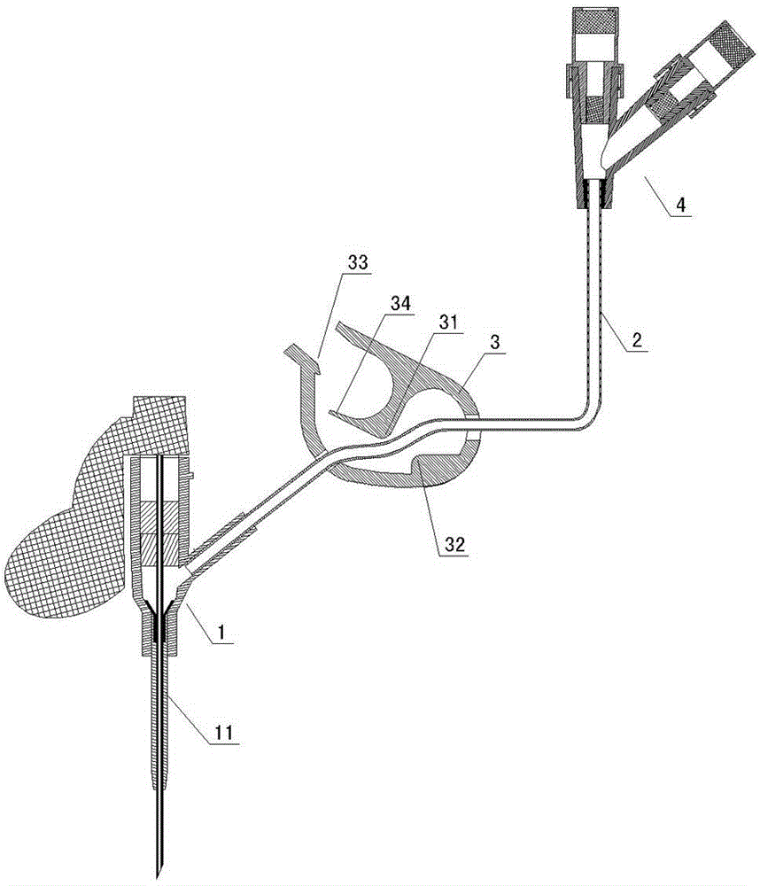
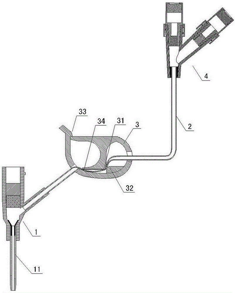
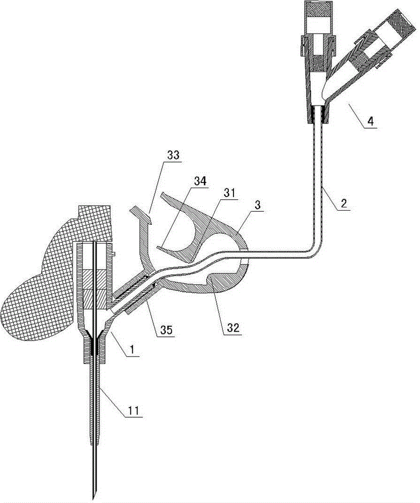
[0020] Such as Figure 1 to Figure 10 As shown, an indwelling needle according to the present invention includes an indwelling hose 11, an indwelling needle base 1, an extension tube base 4, an extension hose 2 connected between the indwelling needle base 1 and the extension tube base 4, and is installed on Extend the liquid stop clamp 3 on the hose 2, and at least one elastic clamp is provided between the clip 31 and the clamp seat 32 of the liquid stop clamp 3 at the front of the upper and lower contacts of the pressure contact part of the liquid stop clamp 3. The elastic compression device 34 with a larger clamping area can form a continuous positive pressure on the extension hose 2 . Above-mentioned elastic pressing device 34 can be as Figure 1 to Figure 6 As shown, the elastic pressing device 34 and the upper contact of the pressing part of the liquid stop clip 3 are integrally formed on the clip 31 and are a transverse U-shaped elastic clamping body located between the...


PUM


Abstract

A remaining needle comprises a remaining hose, a remaining needle seat, an extension hose seat, an extension hose connected between the remaining needle seat and the extension hose seat and a liquid stopping clamp arranged on the extension hose. The front portions of an upper contact and a lower contact located on a pressing touch portion of the liquid stopping clamp between a clamp piece and a clamp seat of the liquid stopping clamp are provided with at least one elastic compression device which has elasticity and larger clamping area and can form continuous positive pressure on the extension hose. According to the remaining needle, due to the fact that the liquid stopping clamp structure with at least two clamping positions is adopted, not only can the clamp piece of the liquid stopping clamp reliably clamp the extension hose to form liquid stopping, but also the continuous positive pressure compression device is utilized to continuously extrude the extension hose at the remaining needle seat end in a large area to enable the extension hose to generate larger deformation, liquid in an extruding pipe enters the remaining hose to play a continuous positive pressure action, therefore, blood return caused by springback siphon of the extension hose due to the liquid stopping clamp can be effectively avoided, the blood can be effectively prevented from flowing back to the remaining hose due to venous pressure fluctuation in blood vessels, and the purpose of preventing thrombus can be achieved.

Description

technical field [0001] The invention relates to an indwelling needle and belongs to the technical field of medical instruments. Background technique [0002] Existing indwelling needles generally include an indwelling hose, an indwelling needle base, an extension tube base, an extension hose connected between the indwelling needle base and the extension tube base, and a liquid stop clip installed on the extension hose. The liquid stop clamp generally includes a clamp seat and a clip piece integrated on the clamp seat. The clamp seat is placed on the extension hose, and the extension hose can be clamped to form a liquid stop through the cooperation of the clip piece and the clamp seat. However, due to the fact that the existing liquid stop clamp will have a rebound after the clip of the liquid stop clamp is loosened in the process of clamping the extension hose, the original clamped extension hose will form a The elastic rebound causes the blood to flow back into the in...

Claims


Application Information

Patent Timeline
Patent Type & Authority Applications(China)
IPC IPC(8): A61M5/158A61M5/175A61M39/28
Inventor 陈伟权韩武洋
Owner ZHANJIANG JIANLIYUAN MEDICAL PROD
Why Eureka
Try Eureka