Mask
A mask and detection device technology, applied in the field of masks, can solve the problems of high leakage rate of masks, inability of masks to block pm2.5 particles, and poor adhesion
- Summary
- Abstract
- Description
- Claims
- Application Information
AI Technical Summary
Problems solved by technology
Method used
Image

Examples
Embodiment 1
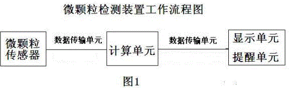
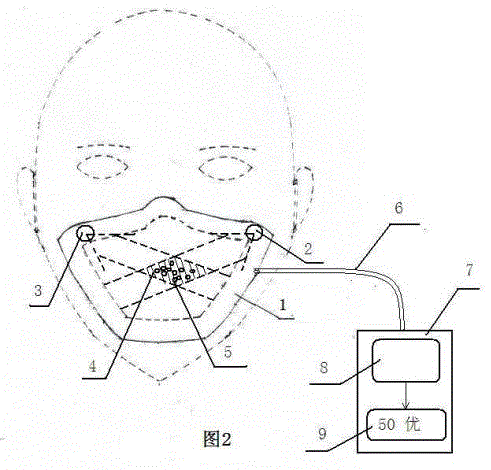
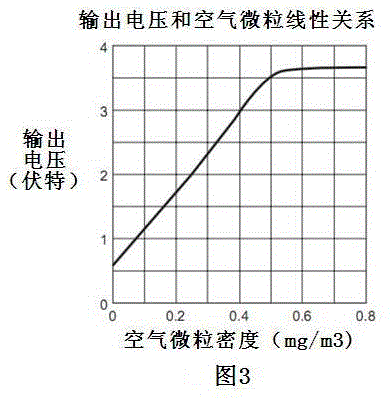
[0035] Embodiment 1: as figure 2 As shown, the mask main body 1 is equipped with a measurement light source 3 which is an infrared light-emitting diode (IRED); the optical sensor 2 is an optoelectronic transistor. The two are arranged diagonally. The specific area where the measurement light source 3 intersects with the optical axis of the optical sensor 2 is a dotted shaded area. Directional emission of LED light to produce reflected light when passing through the airborne particles in a specific area. The optical sensor 2 detects the light reflected by the particles, and transmits the voltage analog signal output by the reflected light to the computing device through the data line. According to the principle that the analog voltage is proportional to the obtained dust concentration, the linear relationship between the voltage analog signal and the air particle concentration (such as image 3 Shown), calculate the concentration or density of particulate matter. Then the ...
Embodiment 2
[0036] Embodiment 2: as figure 2 The measuring light source 3 installed in the shown mask main body 1 is a laser. The specific area where the laser light source intersects with the optical axis of the optical sensor 2 is a dotted shaded area. Scattering occurs when laser light hits particulate matter in the air passing through a specific area. The optical sensor 2 transmits the pulse signal output by the scattered light to the computing device through the data line for digital signal processing and calculation to obtain the concentration or density of particulate matter. Then the calculation result is transmitted to the display device for display.
Embodiment 3
[0037] Embodiment 3: as Figure 4 , Figure 5As shown, the microparticle detection device is completely placed 16 outside the mask. Mask main body 1 has opening. The opening connects the "connecting pipe" 15 to communicate with the microparticle detection device, so that the gas in the part of the mouth mask and the face can reach the detection device. The connecting pipe 15 can be removed and the opening can be closed. The opening in this embodiment is the breathing valve 12 . The connecting pipe end 13 is made of elastic material and can be fastened and closely connected with the breathing valve 12 . The air in the airtight space between the mask main body 1 and the face passes through the air hole 14 of the breathing valve 12 and the connecting pipe 15 set on the outside of the breathing valve 12 to the microparticle detection device along with exhalation.
PUM
 Abstract
Description
Claims
Application Information
 - R&D
- Intellectual Property
- Life Sciences
- Materials
- Tech Scout
- Unparalleled Data Quality
- Higher Quality Content
- 60% Fewer Hallucinations
Browse by: Latest US Patents, China's latest patents, Technical Efficacy Thesaurus, Application Domain, Technology Topic, Popular Technical Reports.
© 2025 PatSnap. All rights reserved.Legal|Privacy policy|Modern Slavery Act Transparency Statement|Sitemap|About US| Contact US: help@patsnap.com