Reinforcing mesh dropping device

A technology of steel mesh and bottom frame, applied in the field of machinery and equipment, can solve the problems of high work intensity, low work efficiency, unfavorable automatic production of cement prefabricated panels, etc., so as to reduce labor intensity, improve production efficiency, and improve economic benefits and social effect of benefit

Inactive Publication Date: 2015-09-23
ZHONGYUAN ENGINEERING COLLEGE
View PDF3 Cites 1 Cited by
  • Summary
  • Abstract
  • Description
  • Claims
  • Application Information

AI Technical Summary

Problems solved by technology

[0005] What the present invention aims to solve is that in the prior art of cement prefabricated slabs, the placement of steel mesh adopts manual methods, which has low work efficiency, high work intensity, and is not conducive to the realization of automatic production of cement prefabricated slabs, etc., thereby providing a work efficiency High-efficiency and low-labor-intensity falling steel mesh device

Method used


Image

  • Reinforcing mesh dropping device
  • Reinforcing mesh dropping device
  • Reinforcing mesh dropping device

Examples


Embodiment 1

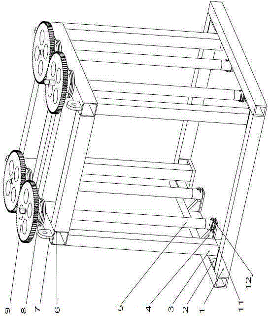
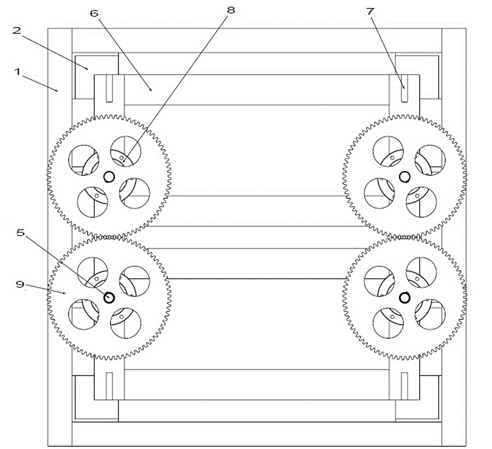
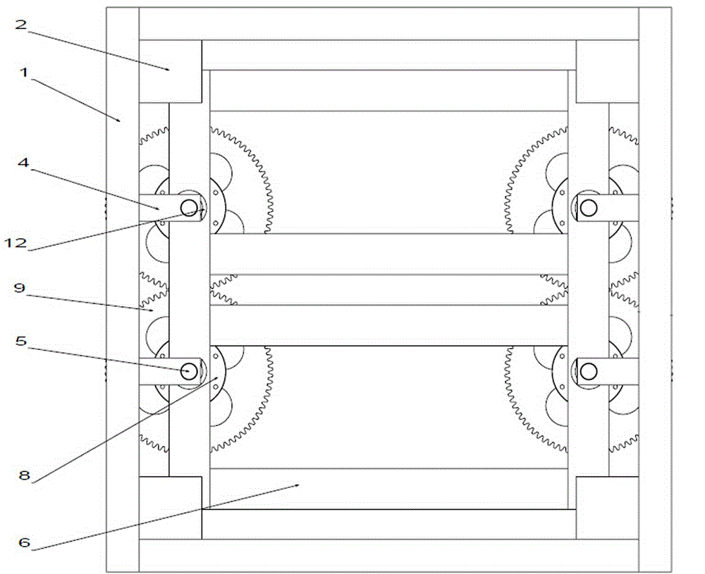
[0023] Embodiment 1: as Figure 1-6 Shown, a kind of steel net falling device comprises bottom frame 1 and upper frame 6, and hanging pan 7 is installed on upper frame 6, and hanging pan can hoist the whole device.

[0024] The corners inside the bottom frame 1 are respectively welded with supporting plates 2 , the lower ends of the columns 3 are installed on the supporting plates 2 , and the upper ends of the columns 3 are connected with the upper frame 6 .

[0025] Two supports 4 are respectively welded inside the two opposite sides of the bottom frame 1, and each support 4 is equipped with a rotating shaft 5, and the lower part of the rotating shaft 5 is provided with a clamping device, and the clamping device includes a sleeve 11. The sleeve 11 is sleeved on the lower end of the rotating shaft 5, and can be rotated synchronously with the rotating shaft 5 tightly, and the sleeve 11 is provided with four layers of claws 12, and the four layers of claws 12 are on the half sid...

Embodiment 2

[0030] Embodiment 2: A kind of steel mesh falling device, comprising a bottom frame and an upper frame, the bottom frame and the upper frame are connected by columns, at least two supports are welded inside the bottom frame, and a rotating shaft is installed on each support, and the rotating shaft The lower part is provided with a clamping device, the upper end of the rotating shaft is provided with a rotating device, and a hanging pan is installed on the upper frame.

Embodiment 3

[0031] Embodiment 3: A device for dropping steel mesh, including a bottom frame and an upper frame, and support plates are respectively welded at the corners inside the bottom frame, the lower ends of the columns are installed on the support plates, and the upper ends of the columns are connected with the upper frame. The inside of the bottom frame is welded with at least two bearings, each bearing is equipped with a rotating shaft, the lower part of the rotating shaft is provided with a clamping device, the upper end of the rotating shaft is equipped with a rotating device, and a suspension plate is installed on the upper frame.

[0032] Wherein, the area of ​​the bottom frame is larger than the area of ​​the upper frame.


PUM


Abstract

The invention discloses a reinforcing mesh dropping device which comprises a bottom frame and an upper frame. The bottom frame and the upper frame are connected through stand columns. At least two supports are welded to the interior of the bottom frame. Each support is provided with a rotating shaft. A clamping device is arranged at the lower portion of each rotating shaft. A rotating device is installed at the upper end of each rotating shaft. Hoist pans are installed on the upper frame. According to the reinforcing mesh dropping device, multiple reinforcing meshes are clamped through multiple layers of clamping jaws on sleeves, the whole device is hoisted to the position where the reinforcing meshes need to be placed through the hoist pans on the upper frame, the rotating shafts are driven to rotate positively and negatively by rotating gears, and therefore the reinforcing meshes are lifted and dropped. The reinforcing meshes do not need to be laid into a die one by one through manual work, the labor intensity of workers is lowered, the production efficiency is improved, the production cost is reduced, very good economic benefits and social benefit are achieved, and automatic production of cement prefabricated slabs is facilitated.

Description

technical field [0001] The invention belongs to the technical field of mechanical equipment, and in particular relates to a steel mesh dropping device used in a production line of cement prefabricated panels in the building material industry. Background technique [0002] The laminated box-mesh girder floor is a new technology of building structure technology innovation. The laminated box-mesh girder floor is made of large cement prefabricated slabs with steel mesh and concrete pouring. [0003] During the pressing and forming process of the cement prefabricated slab, the steel mesh needs to be placed in the mold, and then concrete is poured into the mold for pressing and forming. [0004] At present, the existing production technology uses a manual method to place the steel mesh in the mold. Manually placing the steel mesh in the mold is not conducive to the realization of automatic production of cement prefabricated panels, and the work efficiency of manually placing the s...

Claims


Application Information

Patent Timeline
Patent Type & Authority Applications(China)
IPC IPC(8): B28B23/02
CPCB28B23/022
Inventor 范文捷张忠美刘芳邓清闯郭红战
Owner ZHONGYUAN ENGINEERING COLLEGE
Why Eureka
Try Eureka