A composite joint of steel and concrete strengthened by angle steel

A technology of combining joints and reinforced concrete slabs, applied in the directions of building maintenance, construction, building construction, etc., can solve the problems of flexural bearing capacity and flexural rigidity changes, improve the tensile connection capacity, good economic benefits, and low cost Effect

Active Publication Date: 2018-01-30
HARBIN INST OF TECH
View PDF7 Cites 0 Cited by
  • Summary
  • Abstract
  • Description
  • Claims
  • Application Information

AI Technical Summary

Problems solved by technology

[0003] The purpose of the present invention is to provide a steel-concrete composite joint reinforced with angle steel to solve the problem that the bending capacity and flexural rigidity of the existing traditional steel-concrete composite joints are significantly changed when they are reinforced against collapse

Method used


Image

  • A composite joint of steel and concrete strengthened by angle steel
  • A composite joint of steel and concrete strengthened by angle steel
  • A composite joint of steel and concrete strengthened by angle steel

Examples


specific Embodiment approach 1

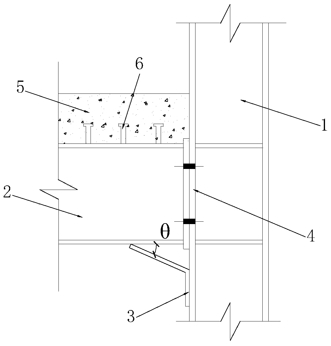
[0010] Specific implementation mode one: combine figure 1 Describe this embodiment, the device of this embodiment comprises steel column 1, steel beam 2, angle steel 3, end plate 4, reinforced concrete plate 5 and shear connection key 6, the vertical section of angle steel 3 and the flange of steel column 1 Connection, the angle steel 3 is located below the joint between the steel beam 2 and the steel column 1 and the free end of the inclined section of the angle steel 3 is against the position of the lower flange of the steel beam 2 and connected with the lower flange of the steel beam 2, the reinforced concrete slab 5 are connected through the shear connection key 6 provided on the steel beam 2, and the shear connection key 6 and the steel beam 2 are connected by welding.

specific Embodiment approach 2

[0011] Specific implementation mode two: combination figure 1 To illustrate this embodiment, the angle θ between the vertical section and the inclined section of the angle steel 3 is 30°-60°, which has good deformation ability and avoids the angle steel participating in the stress during the use stage. Other implementation manners are the same as the specific implementation manner 1.

specific Embodiment approach 3

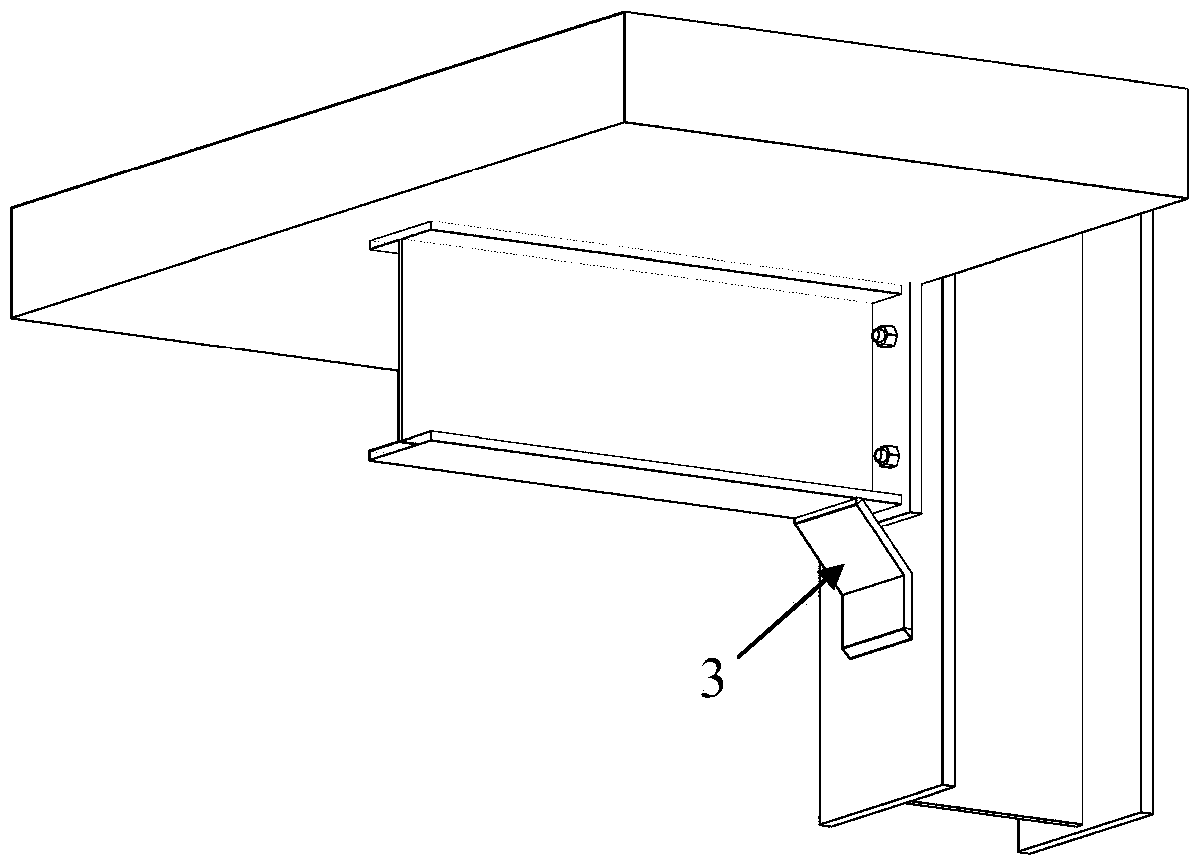
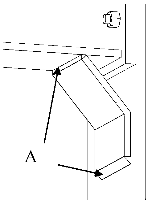
[0012] Specific implementation mode three: combination figure 2 and image 3 Describe this embodiment, the lower end of the vertical section of the angle steel 3 in this embodiment is welded to the flange of the steel column 1, the inclined section of the angle steel 3 is welded to the contact part of the lower flange of the steel beam 2, and the weld seam is at image 3 is displayed as A. The welding connection method is simple and convenient, easy to operate on site, and is suitable for the reinforcement of existing buildings. Other implementation manners are the same as the specific implementation manner 1.


PUM


Abstract

The invention discloses an angle steel reinforced steel and concrete combination joint and relates to the technical field of building structures. The joint solves the problem that when an existing traditional steel and concrete combination joint carries out anti-collapsing reinforcing, flexural capacity and flexural rigidity are obviously changed. According to the scheme, the joint comprises a steel column, a steel beam, angle steel, an end plate, a reinforced concrete plate and an anti-shearing connecting key. The vertical section of the angle steel is connected with the flange of a steel column. The angle steel is placed below the steel beam and the joint of the steel column, and the free end of the oblique section of the angle steel abuts against the position of the lower flange of the steel beam and is connected with the steel beam. The bottom end face of the reinforced concrete plate is connected with the lower flange of the steel beam through the anti-shearing key. The joint is used for anti-collapsing reinforcing of steel-concrete combination joints in built and newly-built structures.

Description

technical field [0001] The invention relates to a steel-concrete composite node reinforced by angle steel with good collapse resistance performance, and relates to the field of building structures. Background technique [0002] Steel and concrete composite joints have the advantages of high bearing capacity, high rigidity and superior seismic performance. Compared with all-welded rigid composite joints, flush end-plate connected semi-rigid composite joints have better rotation capacity and hysteresis performance, and exhibit superior mechanical properties under the action of ground vibration or impact. However, compared with fully welded composite nodes, the safety reserve of semi-rigid composite nodes under special loads is lower. If a component in the node is damaged, it is easy to cause the loss of the bearing capacity of the entire node. In the anti-progressive collapse design of structures, the joints are the most important parts. When the vertical load-bearing compone...

Claims


Application Information

Patent Timeline
Patent Type & Authority Patents(China)
IPC IPC(8): E04B1/58E04G23/02
Inventor 郭兰慧高山刘用
Owner HARBIN INST OF TECH
Why Eureka
Try Eureka