Layered injection device and method for isotopic tracer

A technology of isotope tracer and injection device, which is applied in the field of layered injection device of isotope tracer, can solve the problem of increasing the contradiction between layers in oilfield development, unable to accurately monitor isotope tracer, and unable to accurately control the injection amount of isotope tracer And other issues

Inactive Publication Date: 2015-09-23
TIANJIN DAGANG OILFIELD SHENGDA TECH
View PDF0 Cites 1 Cited by
  • Summary
  • Abstract
  • Description
  • Claims
  • Application Information

AI Technical Summary

Problems solved by technology

The traditional layered injection technology is to inject isotope tracers into multiple oil layers at the same time, which cannot accurately control the injection amount of isotope tracers in each oil layer, and cannot accurately monitor the isotope tracers in each oil layer, which increases the cost of oil field development. Contradictions between layers affect the determination of various parameters of the reservoir and the evaluation of reservoir development

Method used


Image

  • Layered injection device and method for isotopic tracer
  • Layered injection device and method for isotopic tracer
  • Layered injection device and method for isotopic tracer

Examples


Embodiment 1

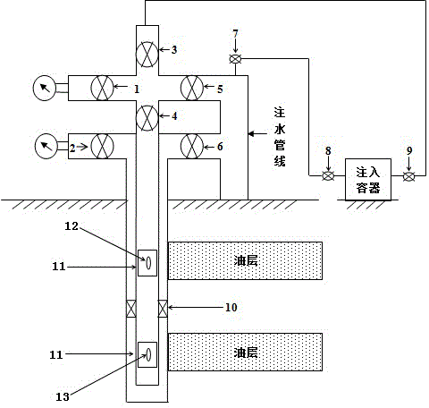
[0031] according to figure 1 As shown, the isotope tracer layered injection device of the present invention includes:

[0032] An injection container, a water injection pipeline and a valve, one end of the injection container is connected to the valve 8, the other end is connected to the valve 9, the other end of the valve 8 is connected to the valve 9, the other end of the valve 9 is connected to the water injection pipeline, the water injection The aboveground part of the pipeline is provided with valves in sequence from top to bottom 3 , valve 1, valve 5, valve 4, valve 2 and valve 6, the layered injection device also includes a packer 10, the packer 10 is located in the underground part of the water injection pipeline, the packer 10 The upper section is provided with an eccentric water distributor 11 communicating with the upper oil layer, and the eccentric water distributor is equipped with a quantitative nozzle 12, and the lower section of the packer is provided with an...

Embodiment 2

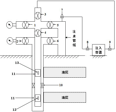
[0034] according to figure 2 As shown, the method for injecting an isotope tracer into the upper oil layer provided by the invention, the specific steps are as follows:

[0035] a. Pull out the quantitative faucet 12 of the eccentric water distributor 11 communicated with the lower oil layer, replace it with a dead plug 13, and close the valve 6;

[0036] b. one end of the valve 9 is connected to the valve 8, and the other end of the valve 9 is connected to the valve 3;

[0037] c. The valve 3 and the valve 5 are closed, the valve 7, the valve 8 and the valve 9 are opened, and pressurized to 35MPa;

[0038] d. Close the valve 7, and inject the isotope tracer tritium water into the layered injection device after the process pressure in the pipe is removed;

[0039] e. The valve 3 and the valve 7 are opened, and the isotope tracer tritium water is injected into the upper oil layer along with the clear water.

Embodiment 3

[0041] according to figure 2 As shown, the method for injecting an isotope tracer into the upper oil layer provided by the invention, the specific steps are as follows:

[0042] a. Pull out the quantitative faucet 12 of the eccentric water distributor 11 communicated with the lower oil layer, replace it with a dead plug 13, and close the valve 6;

[0043] b. one end of the valve 9 is connected to the valve 8, and the other end of the valve 9 is connected to the valve 3;

[0044] c. The valve 3 and the valve 5 are closed, the valve 7, the valve 8 and the valve 9 are opened, and pressurized to 35MPa;

[0045] d. the valve 7 is closed, and after the process pressure in the pipe is removed, the isotope tracer 35 S-Na 2 SO 4 an aqueous solution is injected into the layered injection device;

[0046] e. The valve 3 and the valve 7 are opened, and the isotope tracer 35 S-Na 2 SO 4 The aqueous solution is injected into the upper oil layer along with the clear water.


PUM


Abstract

The invention relates to the field of oil field exploitation, and provides a layered injection device and method for an isotopic tracer. The device comprises an injection container, a water injection pipeline, and a valve. The device also comprises a packer and two eccentric water distributors, and also comprises a quantitative water nozzle and a dead plug, wherein the quantitative water nozzle and the dead plug cooperate with the eccentric water distributors for use. The method comprises the steps: enabling the quantitative nozzle of one eccentric water distributor to be replaced by one dead plug, enabling the other eccentric water distributor to be communicated with an oil layer, slowing injecting the isotopic tracer through the control of the opening and closing of the valve, and enabling the isotopic tracer to be injected to a target oil layer. The device and method can achieve the layered injection of different types of isotopic tracer, can precisely control the injection quantity of the isotopic tracer of the upper and lower oil layers, achieves the accurate monitoring of isotopic tracer of the two oil layers, and has high values for the determining of oil deposit parameter distribution, the development and assessment of a storage layer, and the design, adjustment and enforcement of determining a subsequent development scheme.

Description

technical field [0001] The invention relates to the field of oil field development, in particular to a layered injection device and method for an isotope tracer. Background technique [0002] At present, interwell tracer technology in oilfields has gradually become an important reservoir engineering method in the process of oil production, and is widely used in production practice. Oilfield interwell tracer technology reflects the connection of oil and water wells in the process of reservoir development, and grasps parameters such as the direction of water injection, displacement speed, swept area, and reservoir heterogeneity, so as to guide the design of oilfield production and the later stage of oilfield production adjustment. [0003] At present, for multi-layer reservoirs, isotope tracers are mainly injected by layered injection technology. The traditional layered injection technology is to inject isotope tracers into multiple oil layers at the same time, which cannot ...

Claims


Application Information

Patent Timeline
Patent Type & Authority Applications(China)
IPC IPC(8): E21B47/11E21B49/00
Inventor 姜义
Owner TIANJIN DAGANG OILFIELD SHENGDA TECH
Why Eureka
Try Eureka