Microscopic oil displacement chip with displacement fluid injection volume marking scale in flow-guiding flow passage

A technology of diversion channel and displacing fluid, applied in the petroleum field, can solve the problem of inability to precisely control the injection amount of displacing fluid, and achieve the effect of solving the problem of poor repeatability of experiments

Active Publication Date: 2018-07-06
SOUTHWEST PETROLEUM UNIV
View PDF2 Cites 3 Cited by
  • Summary
  • Abstract
  • Description
  • Claims
  • Application Information

AI Technical Summary

Problems solved by technology

[0004] In view of this, the present application provides a microscopic oil-displacement chip with a scale used to mark the injection volume of the displacement fluid in the diversion flow channel, including the oil displacement area and the corresponding flow channel. The flow channel includes a displacement fluid guide with a scale. The flow channel is used to solve the problem that the existing microscopic oil displacement chip cannot accurately control the injection volume of the displacement fluid during the experiment.

Method used


Image

  • Microscopic oil displacement chip with displacement fluid injection volume marking scale in flow-guiding flow passage

Examples


Embodiment 1

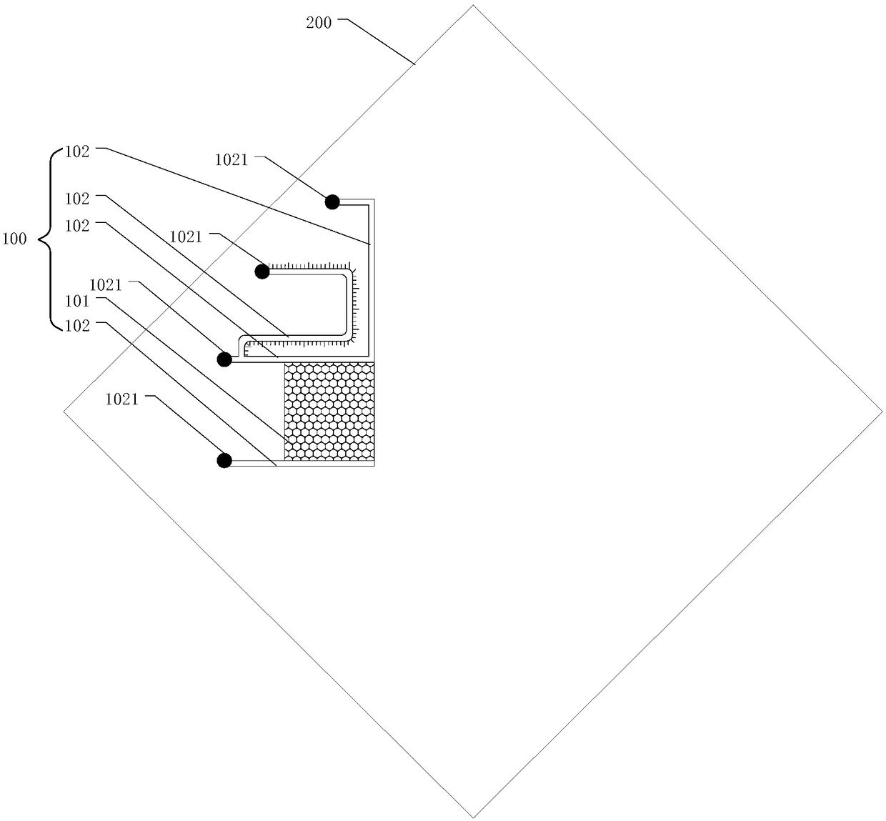
[0023] figure 1 A schematic diagram of a microscopic oil displacement chip provided in the flow channel for marking the injection volume of the displacement fluid provided by the embodiment of the present application.

[0024] Such as figure 1 As shown, the microscopic oil flooding chip provided in this embodiment includes a chip substrate 200 and an oil flooding model 100, and the oil flooding model 100 is used to simulate corresponding water flooding residual oil types and parameters.

[0025] The chip substrate 200 serves as the basis of the entire chip, and its material can be made of hard transparent materials such as glass, so as to observe its seepage and oil displacement process by using its light transmission.

[0026] The oil flooding model includes an oil flooding area 101 and four flow channels 102. One end of the flow channels 102 communicates with the oil flooding area 101, and the other end of each flow channel 102 is connected to the injection port or the prod...


PUM


Abstract

The invention provides a microscopic oil displacement chip with a displacement fluid injection volume marking scale in a flow-guiding flow passage. The microscopic oil displacement chip comprises an oil displacement model arranged on a chip substrate, wherein the oil displacement model comprises an oil displacement area and 4 flow passages; the 4 flow passages are an oil outlet flow passage, a water/oil injection flow passage, a displacement fluid flow-guiding flow passage and an oil washing flow passage respectively; one ends of the flow passages are communicated with the oil displacement area; the other ends of the flow passages are communicated with injection or extraction ports in the chip substrate; the displacement fluid flow-guiding flow passage is used for injecting a displacementfluid into the oil displacement area, and the displacement fluid injection volume marking scale is arranged therein. During an experiment, the scale can be used for intuitively making the injection volume of the displacement fluid; compared with an injection system such as a constant-flow pump, the microscopic oil displacement chip has the advantages as follows: an injection volume error caused byan error of the injection system itself, pipeline expansion, fluid compression and the like is avoided and precise control of the injection volume of the displacement fluid can be achieved through observation on the scale, so that the problem that the experimental repeatability is poor because the conventional chip cannot precisely control the injection volume of the displacement fluid is solved.

Description

technical field [0001] The present application relates to the field of petroleum technology, and more specifically, relates to a microscopic oil displacement chip arranged in a diversion flow channel for marking the injection volume of displacement fluid. Background technique [0002] In order to realize the sustainable and efficient development of oilfields, it is necessary to conduct in-depth research on the displacement and seepage process of chemical displacement fluids. Due to the objective needs of understanding various displacement and seepage mechanisms at the microscopic scale, it is necessary to place microscopic chips in the experimental The device and mold (holder) simulate oil displacement and seepage in reservoir pores. The physical simulation of microscopic oil displacement has become an important means for people to study the mechanism of microscopic oil displacement and seepage. The microscopic oil displacement chip used is obtained by microfluidic etching O...

Claims


Application Information

Patent Timeline
Patent Type & Authority Applications(China)
IPC IPC(8): B01L3/00
CPCB01L3/5027B01L2200/0626B01L2300/0864B01L2300/12
Inventor 冯茹森郭拥军曹苗张新民
Owner SOUTHWEST PETROLEUM UNIV
Why Eureka
Try Eureka