Engine gas inlet duct anti-icing system

An anti-icing system and air intake technology, which is applied in the direction of machines/engines, mechanical equipment, jet propulsion devices, etc., can solve the problems of uncertain heat transfer efficiency, insufficient heating, hot air flow direction, and uncontrollable velocity distribution, etc. question

Active Publication Date: 2015-09-23
AECC COMML AIRCRAFT ENGINE CO LTD
View PDF5 Cites 14 Cited by
  • Summary
  • Abstract
  • Description
  • Claims
  • Application Information

AI Technical Summary

Problems solved by technology

In this structure, the flow direction and velocity of the hot air entering the heat exchange channel and the distribution of the hot air in the heat exchange channel cannot be controlled, and the amount of hot air drawn from the compressor cannot be controlled, which leads to Uncertain thermal efficiency
There are cases where pa

Method used


Image

  • Engine gas inlet duct anti-icing system
  • Engine gas inlet duct anti-icing system
  • Engine gas inlet duct anti-icing system

Examples


Example Embodiment

[0036] The specific embodiments of the present invention will be described in detail below with reference to the accompanying drawings. It should be understood that the drawings shown in the drawings are only preferred embodiments of the present invention, which do not constitute a limitation on the scope of the present invention. Those skilled in the art can make various obvious modifications, variations, and equivalent substitutions to the present invention on the basis of the embodiments shown in the drawings, and these all fall within the protection scope of the present invention.
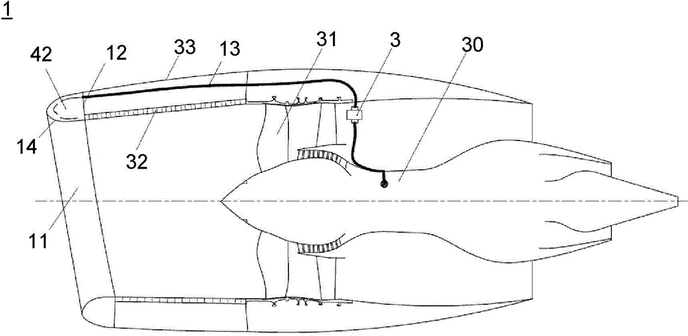
[0037] In this article, the terms "upstream", "downstream" and other terms that indicate orientation are based on the flow direction of the air sucked by the compressor of the engine.

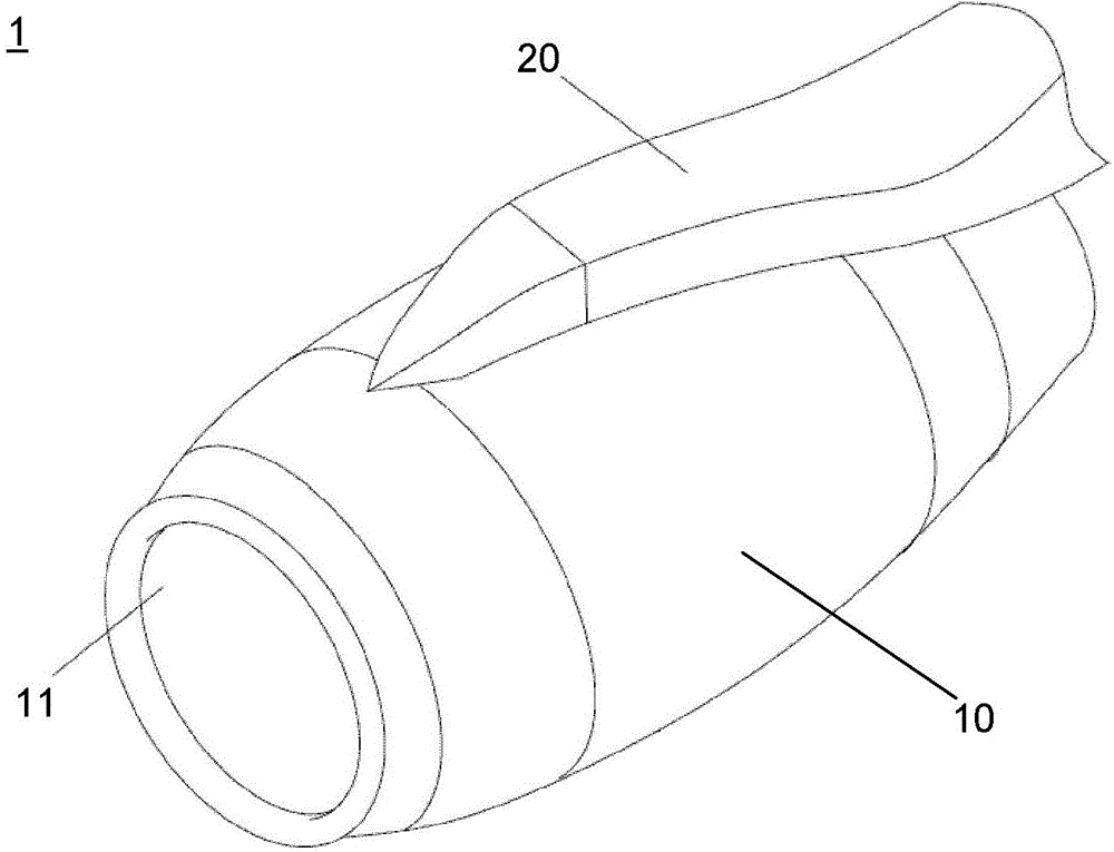
[0038] figure 1 A perspective view of an aero engine 1 is shown. The aircraft engine 1 has a nacelle 10 and a hanger 20. Through the suspension 20, the aero engine 1 can be connected to an appropriate position such...


PUM


Abstract

An engine gas inlet duct anti-icing system comprises a heat exchange passage, a gas guiding pipe, an annular gas distribution pipe and a gas exhausting pipe. The annular gas distribution pipe is arranged in the heat exchange passage, an opening hole is formed in the annular gas distribution pipe, and one end, close to an inlet of a gas inlet duct, of the gas guiding pipe is connected with the opening hole. The annular gas distribution pipe has a throat and a lip mouth; the lip mouth extends along the inlet direction of the gas inlet duct; an adjustable guide vane grid is arranged on the lip mouth, a certain angle is formed between the adjustable guide vane grid and the middle face of the gas inlet duct, and the angle of the guide vane grid is adjusted by a driving mechanism. The engine gas inlet duct anti-icing system can control the flow rate and the flow direction of hot air aiming at different anti-icing conditions, so that a best anti-icing effect can be realized under different anti-icing conditions and different gas inlet duct positions.

Description

technical field [0001] The invention relates to an air intake anti-icing system for an engine. More specifically, it relates to a hot gas anti-icing system for an air intake of an aeroengine. Background technique [0002] When an aircraft is flying in icing conditions, icing may occur on the fuselage. In particular, icing is more likely to occur in the air intake of an aeroengine due to suction. The icing phenomenon of the air inlet of the aeroengine is the most dangerous situation in the icing phenomenon of the aircraft. Icing in the air inlet will change the cross-sectional shape of the air inlet, causing the aerodynamic shape of the air inlet to be destroyed, thereby reducing the thrust of the aeroengine and increasing the load of the aeroengine during flight. What's more dangerous is that the ice layer accumulated in the air intake may fall off and enter the engine with the sucked air, hitting the fan blades at a very high speed. In this way, the compressor of the ae...

Claims


Application Information

Patent Timeline
IPC IPC(8): F02C7/047F02C7/057
Inventor 刘永张正贾文强
Owner AECC COMML AIRCRAFT ENGINE CO LTD
Why Eureka
Try Eureka